
V 2500 P/U 4WD V8-379 6.2L DSL VIN J FI (1987)
14.
Remove throttle shaft assembly and examine for wear or damage. Replace if necessary.
15.
Examine pump housing throttle shaft bushings. If bushings are worn or show signs of leakage, remove pump and send to authorized Stanadyne
distributor for bushing replacement.
16.
Remove seals from throttle shaft. Do not cut seals from shaft, since nicks in seal seat can cause leakage.
17.
Coat new seals with chassis grease or equivalent, and install seals onto throttle shaft.
18.
Slide throttle shaft into pump housing until min-max governor assembly can be installed onto throttle shaft.
19.
Rotate min-max governor assembly downward, hold in this position, then slide throttle shaft and governor into position.
20.
Install new washer, throttle shaft advance cam and a new throttle shaft drive pin. Do not tighten cam screw at this time.
21.
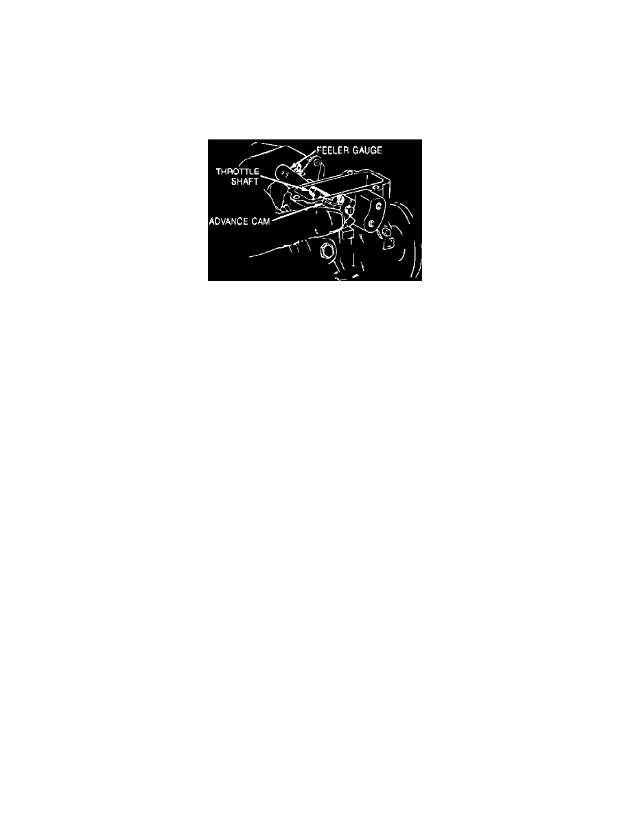
Align throttle shaft advance cam so tool J-29601 can be installed as outlined in Step 7.
Fig. 35 Adjusting throttle shaft advance cam
22.
Insert a .005 inch feeler gauge between throttle shaft white washer and pump housing, then squeeze throttle shaft and torque cam screw to 30 inch
lbs., Fig. 35. Apply Loctite 290 or equivalent to secure screw, then remove tool.
23.
Install guide stud and new washer, ensuring upper extension of metering valve spring is positioned over guide stud. Torque guide stud to 85 inch
lbs.
24.
Hold throttle in idle position, then install new seal onto pump cover. Install cover onto injection pump, then torque attaching screws to 33 inch lbs.
25.
Install vacuum regulator valve or TPS switch, then reconnect battery ground cables.
26.
Turn ignition switch to ``Run'' position, then momentarily connect pink wire to solenoid. A clicking noise should be heard whenever wire contacts
solenoid. If clicking noise is evident, connect fuel solenoid and housing pressure cold advance electrical leads and proceed to Step 28. If clicking
noise is not evident, proceed to next step.
27.
Remove cover. With ignition switch in ``Run'' position, ground solenoid lead and connect pink wire. The solenoid should activate and move the
linkage. If solenoid does not activate, replace it. Repeat steps 26 and 27.
28.
Reinstall throttle cable bracket, detent cable and fast idle solenoid.
29.
Reinstall throttle cable and return springs.
30.
Ensure timing marks on injection pump and housing are aligned, then tighten attaching nuts. Reconnect fuel return line.
31.
Start engine and check for leaks. Engine may idle roughly due to air in the injection system. Allowing engine to idle for several moments will
usually purge system of air. If not, shut engine off and allow air bubbles to rise to the top of the injection pump, then restart engine.
32.
Remove intake manifold screens, then reinstall intake and air cleaner.