
V 3500 P/U 4WD L6-292 4.8L (1987)
Cruise Control Switch: Testing and Inspection
Mode Control Assembly
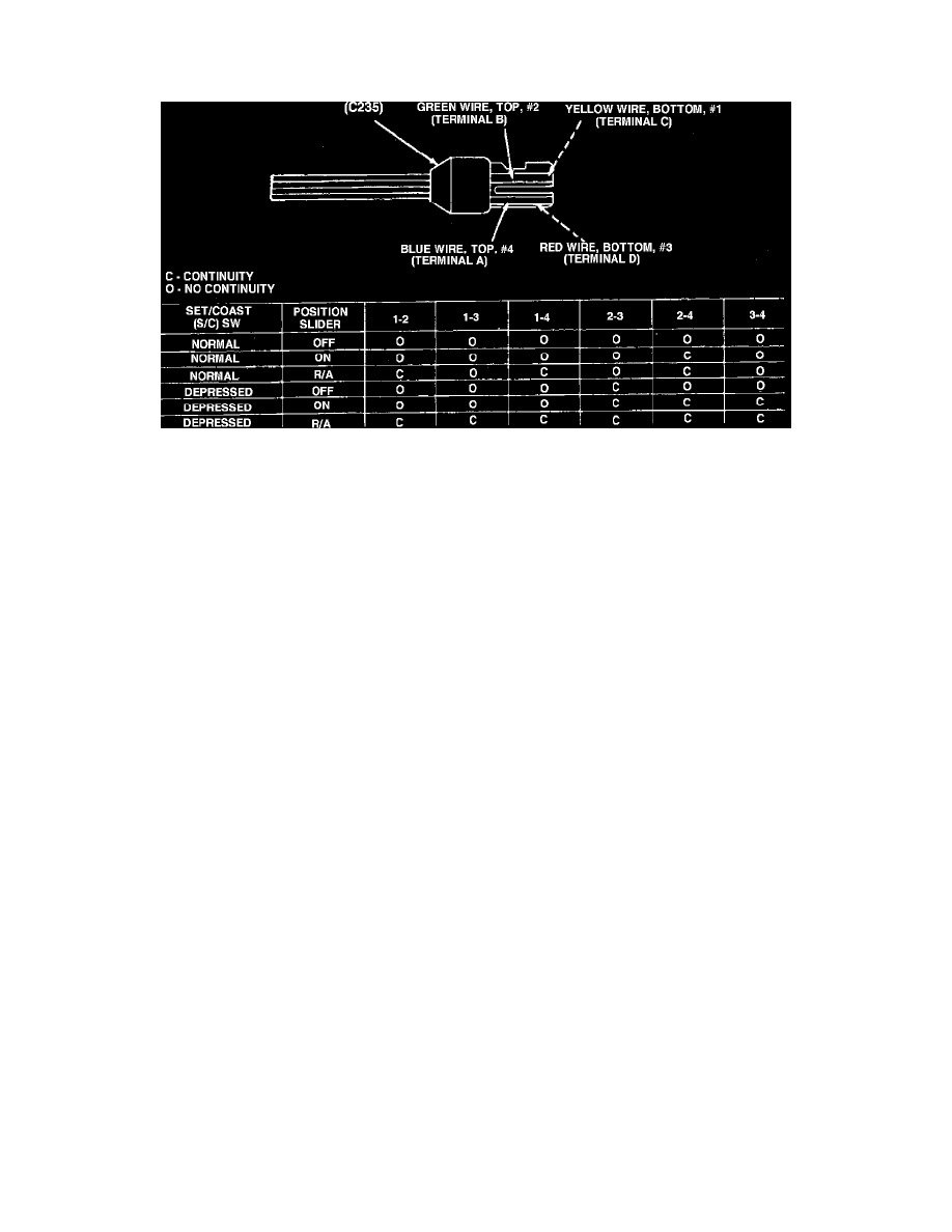
Fig. 18 Mode control continuity test. Custom Cruise III
1.
Disconnect mode control electrical connector from main harness connector at base of steering column.
2.
Test continuity between switch connector terminals using an ohmmeter.
3.
If continuity is not as shown in Fig. 18, switch is defective.
4.
Check continuity between each switch connector terminal and ground. If meter indicates continuity, check for pinched switch harness in steering
column mast jacket.