
Yukon/Denali 2WD V8-4.8L VIN V (2005)
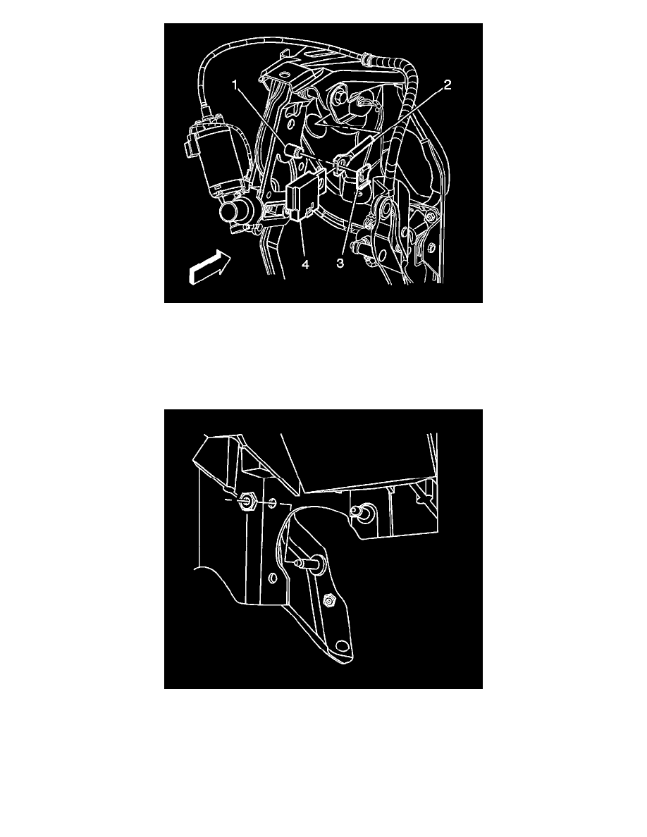
11. Install the brake pedal pushrod (2) and the stop lamp switch (4) to the brake pedal.
12. Install the pushrod retaining clip (3) to the brake pedal pin (1).
13. Connect the electrical connectors to the following components:
-
The adjustable pedals motor assembly
-
The memory sensor connector, if equipped
-
The pedal position sensor
-
The accelerator wiring harness connector
14. Position the replacement I/P reinforcement brace and install the upper and lower bolts to maintain the position of the brace. The lower bolt may be
removed after the brace is in position.
15. Install the upper I/P reinforcement brace nut to the bolt.
IMPORTANT: Do not allow the assembly tool speed to exceed 350 RPM on fasteners with an adhesive patch.
Tighten the nut to 22 N.m (16 lb ft).