
Yukon/Denali 2WD V8-4.8L VIN V (2005)
9. Remove the rotor retaining push nuts from the wheel studs, if applicable.
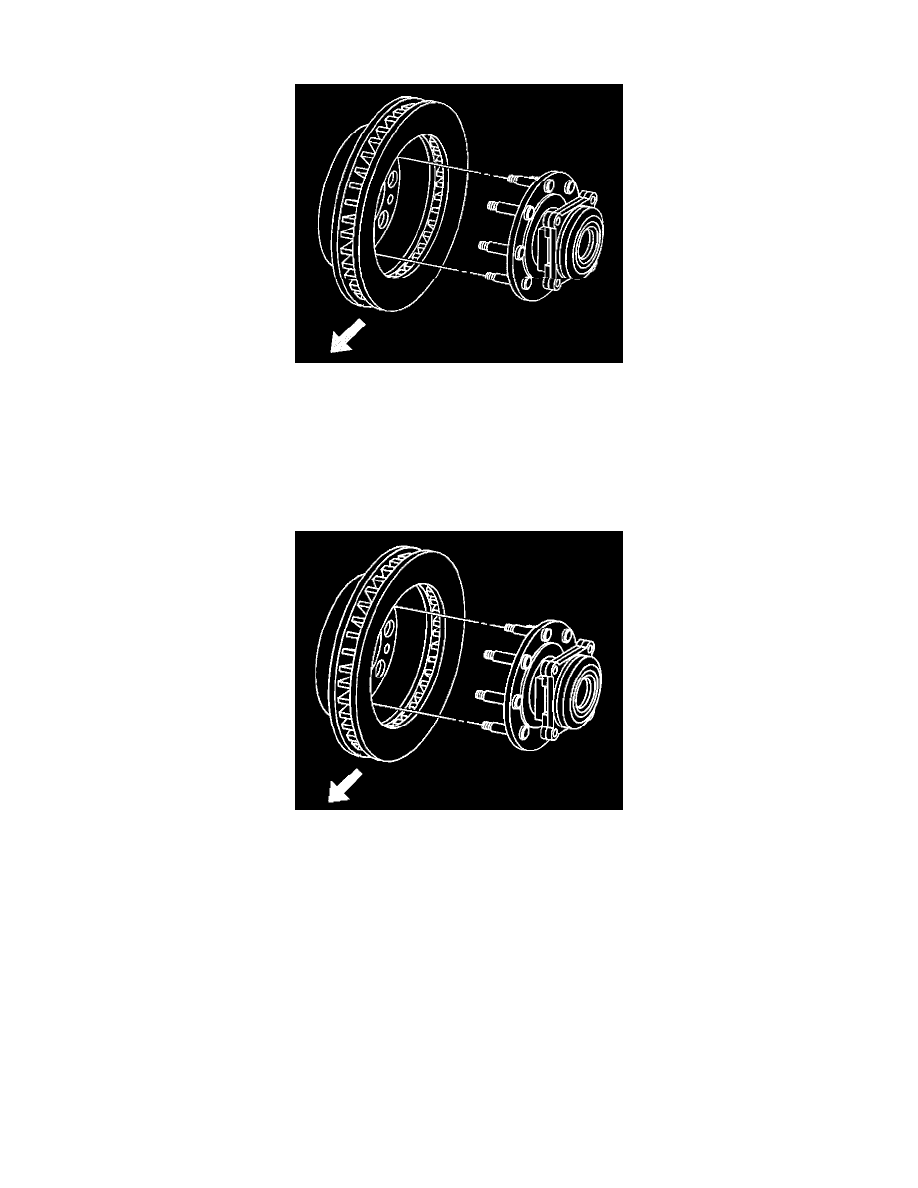
10. It may be necessary to strike the end of the hub or the rotor with a deadblow hammer to separate the rotor from the hub.
11. Remove the rotor.
12. If the rotor is difficult to remove due to corrosion in the hub area use the following procedure to remove the rotor.
^
Clean all the surface areas and the threaded holes of contamination.
^
Generously apply penetrating oil or the equivalent to the hub/rotor area.
^
Insert (2) M10 x 1.5 bolts into the threaded holes of the rotor.
^
Tighten both bolts evenly to force the rotor from the hub.
Installation Procedure
Important: Whenever the brake rotor has been separated from the hub/axle flange, any rust or contaminants should be cleaned from the hub/axle
flange and the brake rotor mating surfaces. Failure to do this may result in excessive assembled Lateral Runout (LRO) of the brake rotor, which could
lead to brake pulsation.
1. Use the J42450-A to clean all rust and contaminants from the mating surface of the hub flange.
2. Use the J41013to clean all rust and contaminants from the inside diameter of the hat section of the brake rotor to prevent any foreign material from
getting between the brake rotor and the hub flange.
3. Inspect the mating surfaces of the hub/axle flange and the rotor to ensure that there are no foreign particles or debris remaining.
Important: If the rotor was removed using the jack screw method you must ensure that the hub flange is free of nicks or marks caused by this
procedure. Remove all raised nicks or marks before installing the rotor.
4. Align the rotor to its original position on the hub, if applicable, and install the rotor.
5. If the brake rotor was removed and installed as part of a brake system repair, measure the assembled Lateral Runout (LRO) of the brake rotor to
ensure optimum performance of the disc brakes. Refer to Brake Rotor Assembled Lateral Runout (LRO) Measurement.
6. If the brake rotor assembled LRO measurement exceeds the specification, bring the LRO to within specifications. Refer to Brake Rotor Assembled
Lateral Runout (LRO) Correction.
7. Install the caliper and caliper mounting bracket assembly.
8. Perform the following procedure before installing the brake caliper bracket mounting bolts.