
Yukon/Denali 4WD V8-4.8L VIN V (2005)
is only intended for emergency use.
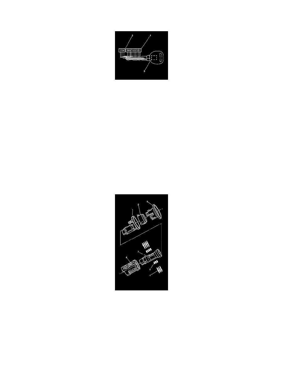
CUTTING KEYS
You can obtain the key code from the 4-digit number on the key tag that accompanies the original master and valet keys. The 4-digit key code cross
references to the cut and tumbler sequence. The keys have 10 key cut positions (1) and 4 key cut depths (2). Key cut positions are numbered 1-10,
counting from the head of the key to the tip. The key cut depths are 1 through 4, cut depth number 1 is the deepest cut. The key transponder (3) in the
master and valet key must be programmed to the vehicle. Refer to appropriate service procedure for programing the keys to the vehicle.
1. Cut a blank key to the proper depth and sequence of each of the tumbler positions.
2. Inspect the mechanical operation of the key in the lock cylinders, in the doors, the ignition switch, the rear compartment lid and any storage
compartments:With each side of the key pointing up inside the lock, inspect the operation of the lock in both directions.
-
Turn the key both directions in each lock cylinder.
-
Turn the key with each side of the key pointing upward in each lock cylinder.
3. If replacing a master or valet key, program the key transponder to the vehicle.
LOCK CYLINDER TUMBLER OPERATION
Each of the four cut depths on the key has corresponding tumblers, sometimes referred to as plates or wafers. The tumbler depth number is stamped on
the tumblers for identification. The IP storage compartment lock cylinder also requires a retainer tumbler. The retainer tumbler is not moved by the
key, its function is to retain the IP storage compartment lock cylinder in the lock assembly.
ASSEMBLING AND CODING IGNITION LOCK CYLINDER
The ignition lock cylinder only uses seven of the ten cut positions, 3 through 9. The tumbler positions are staggered from side to side, 4 on one side
and three on the other.
1. Hold the cylinder (7) so that the side with 4 tumbler spring wells is facing up.
2. Insert tumbler springs (5) into the 4 spring wells.
3. The first tumbler to be loaded will be the 3rd key cut position - the 3rd number in the key code. Install the first tumbler (4) in the slot nearest the
front of the lock cylinder, this is the side the key would be inserted from.
4. Install the three remaining tumblers on this side of the lock cylinder, key cut positions 5, 7 and 9.
5. Snap the tumblers into place with light hand pressure.
6. Check for correct loading of the tumblers (4) by inserting the key into the cylinder (7). All of the tumblers should be flush with the lock cylinder.
7. Turn the cylinder (7) so that the side with the 3 tumbler spring wells is facing up.
8. Insert the tumbler springs (5) into the three spring wells.
9. Install the tumbler (4) for the key cut position 4 into the slot nearest to the front of the lock cylinder.
10. Install the 2 remaining tumblers, key cut positions 6 and 8, on this side of the lock cylinder.