
Yukon 2WD V8-393 6.5L DSL Turbo VIN S (1995)
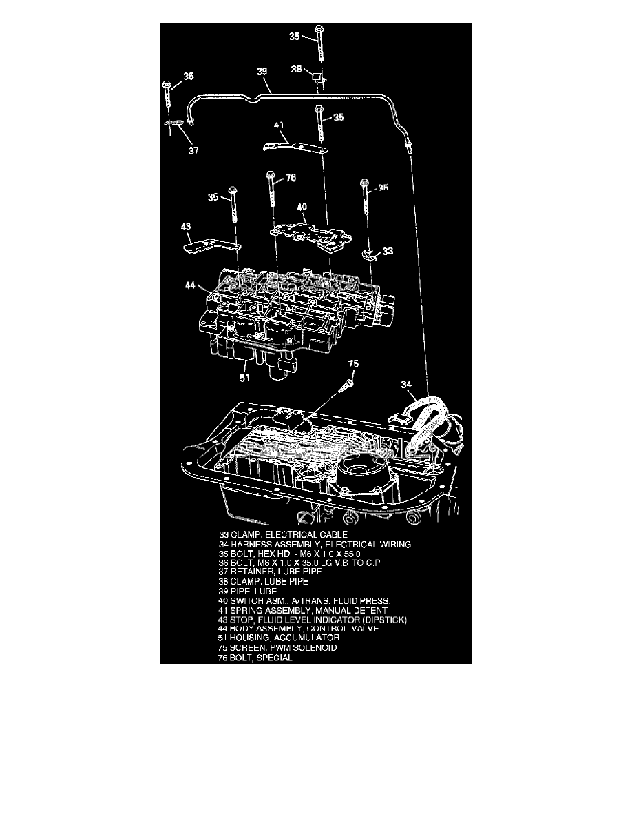
Fig. 10 Control Valve Assembly
3. Remove bolts from valve body assembly, manual detent spring and roller assembly, Fig. 10. Ensure five O-rings are attached to pressure
manifold assembly.
4. Remove pressure manifold assembly.
5. Remove wiring clips, fluid level indicator stop, lube pipe, lube pipe retainer and clamps.
6. Remove control valve assembly including accumulator housing assembly, valve body gaskets, spacer plate and accumulator gasket.
7. Remove eight check balls from case passages.
8. Remove two speed sensors, bracket assemblies and PWM solenoid screen.