
Yukon 2WD V8-5.3L (2007)
4. Ignition OFF, test for an open, for a high resistance, for a short to ground, or for a short to voltage in the cruise control switch signal circuit.
5. Test the component. If the circuits and the component tests are normal, replace the BCM.
COMPONENT TESTING
CAUTION: Refer to SIR Caution.
Disable the inflatable restraint steering wheel module when performing this diagnostic.
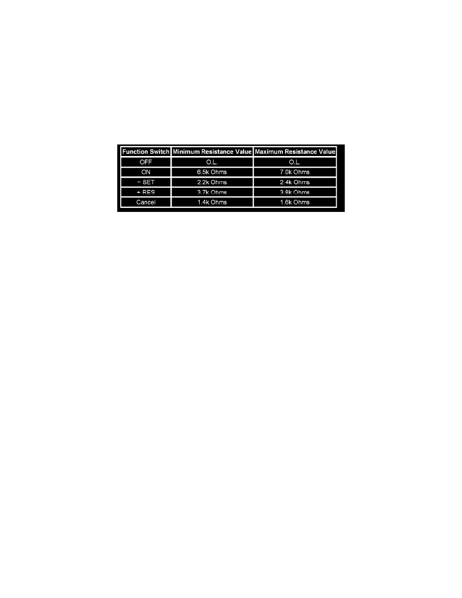
IMPORTANT: The cruise control ON/OFF switch must be ON in order to properly measure the resistance of the - SET, the + RES, and the Cancel
switches.
1. With the ignition OFF, remove the inflatable restraint steering wheel module.
2. With the ignition OFF, disconnect C277 at the inflatable restraint steering wheel module coil.
3. Measure the resistance between terminals 1 and 3 at the cruise control switch side of the connector. Individually activate and hold each cruise
control function switch and compare the resistance reading to the values on the schematic for the ON/OFF, - SET, the + RES, and the Cancel
switches.
-
If any of the resistance measurements for the OFF, ON, - SET, + RES, and Cancel switches are not within the listed resistance values, replace
the cruise control switch assembly.
REPAIR INSTRUCTIONS
Perform the Diagnostic Repair Verification after completing the diagnostic procedure.
-
Steering Wheel Control Switch Assembly Replacement
-
Control Module References for BCM replacement, setup, and programming. See: Testing and Inspection/Programming and Relearning See:
Powertrain Management/Computers and Control Systems/Testing and Inspection/Diagnostic Trouble Code Tests and Associated
Procedures/Verification Tests and Procedures
Cruise Control Switch Indicator Inoperative
CRUISE CONTROL SWITCH INDICATOR INOPERATIVE
DIAGNOSTIC FAULT INFORMATION
Perform the Diagnostic System Check - Vehicle prior to using this diagnostic procedure. See: Testing and Inspection/Initial Inspection and Diagnostic
Overview/Diagnostic System Check - Vehicle
CIRCUIT/SYSTEM DESCRIPTION
The body control module (BCM) monitors the cruise control indicator switch. When the cruise on/off switch is pressed ON, the cruise control switch
is closed and the signal circuit is low. When the cruise on/off switch is pressed OFF, the cruise control switch is open and the signal circuit is high.
CIRCUIT/SYSTEM TESTING
1. Ignition OFF, disconnect the cruise control switch assembly.
2. Connect a fused jumper between the voltage signal circuit and the low reference circuit.
3. Ignition ON, observe the Cruise On/Off Switch parameter.
-
If the Cruise On/Off Switch parameter displays ON, replace the cruise control switch assembly.
-
If the Cruise On/Off Switch parameter displays Off, test the voltage signal circuit and the low reference circuit for an open, or for a high
resistance.
-
If all circuits test normal, replace the BCM.
REPAIR INSTRUCTIONS
Perform the Diagnostic Repair Verification after completing the diagnostic procedure.
-
Steering Wheel Control Switch Assembly Replacement
-
Control Module References for BCM replacement, setup, and programming. See: Testing and Inspection/Programming and Relearning See:
Powertrain Management/Computers and Control Systems/Testing and Inspection/Diagnostic Trouble Code Tests and Associated
Procedures/Verification Tests and Procedures