
Yukon 4WD V8-5.3L (2008)
Auxiliary Power Outlet: Testing and Inspection
Power Outlet Receptacle Inoperative
Power Outlet Receptacle Inoperative
Diagnostic Instructions
*
Perform the Diagnostic System Check - Vehicle prior to using this diagnostic procedure. See: Testing and Inspection/Initial Inspection and
Diagnostic Overview/Diagnostic System Check - Vehicle
*
Review Strategy Based Diagnosis for an overview of the diagnostic approach.
*
Diagnostic Procedure Instructions provides an overview of each diagnostic category.
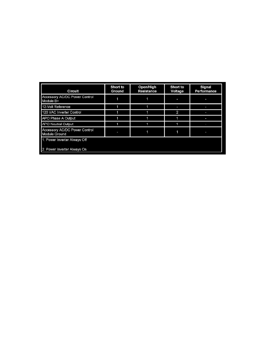
Diagnostic Fault Information
Circuit/System Description
Battery voltage is supplied to the accessory AC/DC power control module from the 25-amp PWR OUTLET fuse located in the underhood fuse block.
The accessory AC/DC power control module is grounded directly to the right rear B-pillar. When the ignition is turned ON, ignition voltage is supplied
to the 120-volt power receptacle using the ignition 3 voltage circuit. When a 120-volt AC powered device is plugged into the 120-volt power receptacle,
with the ignition ON, the normally open plug inserted switch, located internally in the 120-volt power receptacle, closes. The accessory AC/DC power
control module detects an ignition voltage signal on the 120 VAC Inverter control circuit and the accessory AC/DC power control module enables the
120 AC volts to the 120-volt power receptacle.
Circuit/System Verification
Ignition ON, verify an AC voltage powered device functions when plugged into the 115 VAC power outlet receptacle.
Circuit/System Testing
1. Ignition OFF, disconnect the harness connector X2 at the accessory AC/DC power control module.
2. Test for less than 1.0 ohm between the ground circuit terminal 1 and ground.
^
If greater than the specified range, test the ground circuit for an open/high resistance.
3. Ignition ON, verify that a test lamp illuminates between the B+ circuit terminal 2 and ground.
^
If the test lamp does not illuminate, test the B+ circuit for a short to ground or an open/high resistance.
4. Ignition OFF, connect the harness connector X2 and disconnect the harness connector at the 115 VAC auxiliary power outlet.
5. Ignition ON, test for B+ voltage between the IGN I/II circuit terminal 4 and ground.
^
If less than the specified range, test the IGN I/II circuit for a short to ground or an open/high resistance.
6. Ignition OFF, connect the harness connector at the 115 VAC auxiliary power outlet and disconnect the harness connector X1 at the accessory
AC/DC power control module.
7. Ignition ON, insert an AC voltage powered device into the 115 VAC auxiliary power outlet and test for B+ voltage between the 120 VAC inverter
control circuit terminal 2 and ground.
^
If less than the specified range, test the control circuit for a short to ground or an open/high resistance. If the circuit tests normal, test or replace