
Yukon 4WD V8-5.3L (2008)
Alignment: Testing and Inspection
Trim Height Inspection
Trim Height Measurements
Trim height is a predetermined measurement relating to vehicle ride height. Incorrect trim heights can cause bottoming out over bumps, damage to the
suspension components, and symptoms similar to wheel alignment problems. Check the trim heights when diagnosing suspension concerns and before
checking the wheel alignment.
Perform the following before measuring the trim heights:
*
Ensure the vehicle is on a level surface, such as an alignment rack.
*
Ensure that the suspension is fully supporting the vehicle.
*
Remove the alignment rack floating pins.
*
Set the tire pressures to the pressure shown on the certification label. Refer to Vehicle Certification, Tire Placard, Anti-Theft, and Service Parts ID
Label .
*
Inspect the fuel level. Add additional weight if necessary to simulate a full tank.
*
To ensure proper weight distribution make sure the rear storage compartment is empty.
*
Close all doors, lift gate/trunk and the hood.
Z Height Measurement
Important: K models only-The Z height must be adjusted before the alignment.
The Z height dimension measurement determines the proper ride height for the front end of the vehicle. Vehicles equipped with torsion bars use a
adjusting arm in order to adjust the Z height dimension. Vehicles without torsion bars have no adjustment and could require replacement of suspension
components.
Important: All dimensions are measured vertical to ground. Cross vehicle Z heights should be within 12 mm (0.47 in) to be considered
correct.
1. Jounce the front and rear suspension to obtain at least 38 mm (1.5 in) deflection, then allow the vehicle to settle.
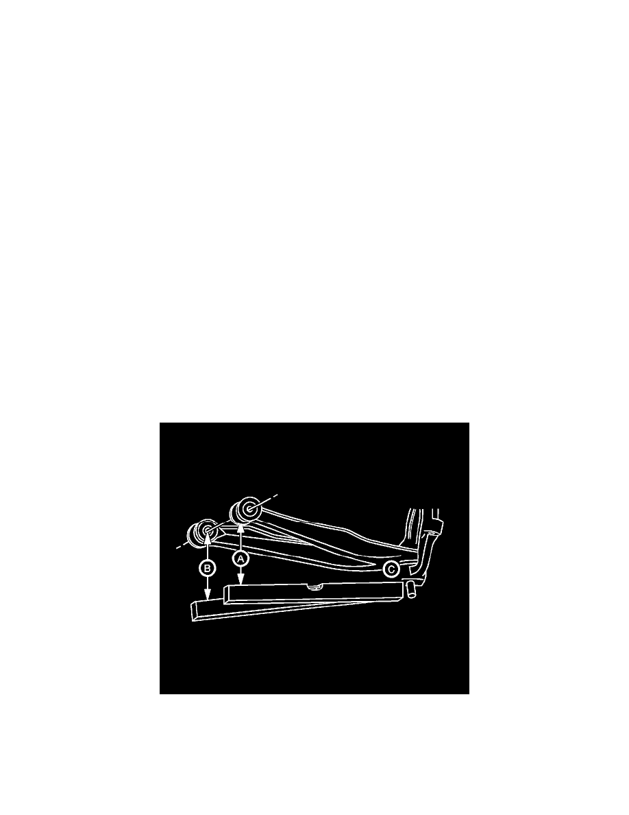
2. Set the top edge of the level on the reference surface of the steering knuckle (C) and extend the level directly under the rear end of the front
attachment bolt of the lower control arm (A).
3. While keeping the level in contact with the knuckle reference surface, adjust the level up/down until the bubble indicates it is horizontally level.
4. Extend a tape measure straight down from the center of the attachment bolt. The point where the tape measure and the level intersect is your first
measurement.
5. Keep the top edge of the level on the reference surface of the steering knuckle (C) and move the level directly under the front end of the rear
attachment bolt of the lower control arm (B).