
Yukon 4WD V8-6.5L DSL Turbo VIN S (1997)
1. All parts for cracks, distortion, or other structural damage. Replace parts or assemblies that are cracked. bent, or otherwise damaged.
2. Threaded parts for stripped, crossed, or otherwise damaged threads. Replace the parts with thread damage that cannot be cleaned up using a
suitable tap or die. Replace any hardware items that have damaged threads.
3. Solenoid assembly (19) for cut or torn boot. If the boot is damaged, replace the solenoid assembly.
4. Clutch drive assembly (34) for the following and replace the clutch drive assembly if damaged.
^
Pinion gear turns roughly or turns in both directions.
^
Pinion gear teeth are broken or show evidence of step wear.
^
The shift lever collar shows deep scoring or other damage
5. Brush holder assembly (7) for the following. Replace if damaged:
^
Loose riveted joints.
^
Cracked or broken insulation.
6. Brushes (5 and 8) for excessive wear.
^
Minimum allowable brush length is 12 mm (0.472 in). Replace excessively worn brushes in sets.
7. Drive end housing bushing (37) for scoring or other damage. Replace the damaged bushing, refer to "Repair Procedures".
8. Ball bearings (12,14, and 32) as follows:
A. Hold the armature (13) or driveshaft (31) and slowly rotate the outer bearing race by hand.
B. Check that the bearing turns freely without binding or the feel of flat spots.
C. Replace damaged bearings, refer to "Repair Procedures".
9. Armature assembly (13) for the following:
^
Gear teeth that are broken, or that show evidence of step wear or root interference.
^
Rough commutator surface. Polish with 400 grit polishing cloth if necessary. Thoroughly clean metal dust from between the commutator
bars. If the commutator surface cannot be repaired in this manner, replace the armature assembly. Do not turn the commutator in a lathe.
^
Worn commutator. Replace the armature assembly if the commutator outer diameter is less than 36 mm (1.378 in) or if the undercut depth
at any point is less than 0.2 mm (0.008 in). Do not undercut the insulation.
10. Driveshaft (31) for the following. Replace the drive shaft if damaged:
^
Scored or damaged shaft where it turns in the bushing (37).
^
Internal gear with teeth broken or showing evidence of step wear.
^
Damaged spline. The clutch drive assembly must slide smoothly and easily over the full length of the spline.
Component Electrical Testing
Perform the following electrical tests on the solenoid, armature, and frame and field assemblies to determine their serviceability.
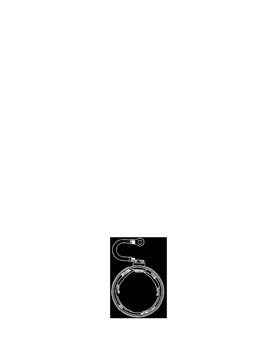
1. Using an ohmmeter, check the windings of the solenoid assembly for continuity as follows:
^
Check the resistance of the solenoid pull-in and hold-in windings in series by measuring the resistance between the motor terminal and the
solenoid case (Figure 9). Resistance should be about 1.95 ohms.
^
An extremely high resistance reading indicates a break or fault in the winding continuity. A very low resistance reading indicates a short or
ground in the winding circuit. Either condition is cause for replacement of the solenoid assembly.
2. Check the armature assembly as follows for shorts, opens, or grounds.
^
Rotate the armature in a growler holding a steel strip such as a hacksaw blade against the armature. If a short circuit is present, the steel strip
will vibrate in that area.
^
Check the armature for grounds using a self-powered test lamp or ohmmeter. There should not be any continuity between the armature shaft
and any point on the commutator.
^
Check for opens by visually inspecting the points where the armature conductors join the commutator. A poor connection often will be
indicated by signs of arcing or burning of the commutator.
^
Replace armatures that are shorted, grounded, or show evidence of opens.
Frame And Field Assembly
3. Check the frame and field assembly for grounds or opens.
A. Visually inspect the field coil connections for opens between the field terminal and the connection points for insulated brushes on the field coil