
Yukon 4WD V8-6.5L DSL Turbo VIN S (1997)
1. Tire and wheel assembly. Unload the torsion bar, using J 36202. Mark the adjuster bolt for installation.
a. Slide the bar forward to remove the adjuster arm.
2. Adjuster arm (186).
3. Outer axle shaft nut (120) and washer (119) from the hub assembly (114).
4. Brake caliper.
5. Brake rotor.
6. Lower shock bolt from control arm and compress shock.
7. Inner tie rod end from the relay rod, using J 24319-01.
-
Support the lower control arm with a jack.
8. Stabilizer link from control arm.
9. Drive axle (121) from hub.
10. Cotter pin and nut from the upper ball joint (115).
11. Upper ball joint (115) from knuckle (117) using J 36607.
12. Nuts (170 and 165) and washer (162).
13. Bolts (166 and 160).
14. Lower control arm (93) and knuckle (117) as a unit.
15. Front bushing (167)
-
Unbend crimps, using a punch.
-
Remove the bushing, using J 36618-2, J 9519-23, J 36618-4, and J 36618-1.
16. Rear bushing (163) (no crimp).
-
Remove using J 36618-5, J 36618-3, J 36618-2, and J 9519-23.
-
Replace lower control arm if the bushings are worn or damaged (K1 and K2 vehicles).
INSTALLATION
CAUTION: Always use the correct fastener in the proper location. When you replace a fastener, use ONLY the exact part number for that
application. The manufacturer will call out those fasteners that require a replacement after removal. The manufacturer will also call out the fasteners
that require thread lockers or thread sealant. UNLESS OTHERWISE SPECIFIED, do not use supplemental coatings (paints, greases, or other
corrosion Inhibitors) on threaded fasteners or fastener joint interfaces. Generally, such coatings adversely affect the fastener torque and joint clamping
force, and may damage the fastener. When you install fasteners, use the correct tightening sequence and specifications. Following these instructions
can help you avoid damage to parts and systems.
Install or connect the following:
1. Front bushing, using J 36618 and J 9519-23.
-
After installing the bushing, crimp it in place (K3 vehicle only).
2. Rear bushing, using J 36618 and J 9519-23.
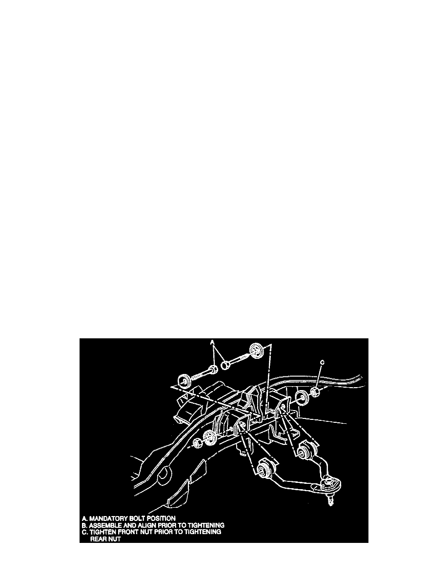
3. Lower control arm (93) and knuckle assembly (117) to the crossmember (171) and the frame bracket (164).
-
Install the front leg of the lower control arm into the crossmember (171) before installing the rear leg into the frame bracket (164).
4. Bolts (166, 160) in the direction shown.