Yukon Denali 2WD V8-6.0L Hybrid (2010)

Circuit/System Description
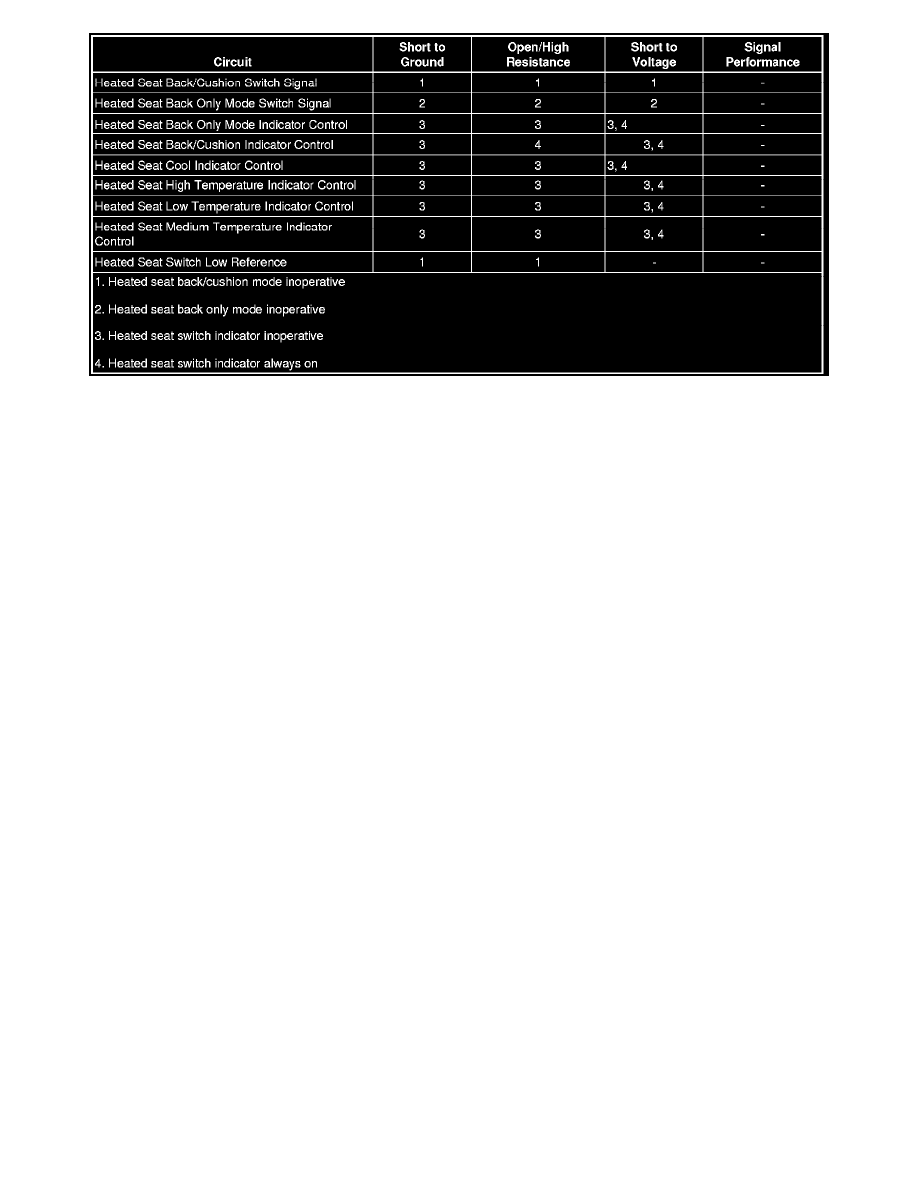
The driver and front passenger heated seats are controlled by separate heated seat switches located on the door panels. When a heated seat switch is
pressed, ground is momentarily applied through the switch contacts and the switch signal circuit to the door lock/window switch. In response to this
signal, the door lock/window switch sends a serial message to the memory seat module (MSM) or heated seat module (HSM) indicating the heat seat
request. The module then applied battery voltage to the seat cushion and seat back heater elements through a common voltage supply circuit. Each
individual heater element is grounded by the module through separate low side drive control circuits. The heater element control circuits are pulse width
modulated (PWM) to ground by the module in order to control the seat temperatures by regulating the current flow through the heater elements. The
MSM/HSM relies on 4 independent inputs from temperature sensors (thermistors) located in the seat back and seat cushion of the driver and passenger
seats. The temperature sensor resistance varies based on the temperature of the heating element causing the signal circuit voltage to change. Once the
seat reaches the switch set temperature, the MSM/HSM will then cycle the control circuits of the heating elements ON and OFF in order to maintain the
desired seat temperature based on the feedback voltage from the sensors. The MSM/HSM then monitors the current flow through the heating elements
and the of rate change of the temperature sensor to verify correct heated seat operation.
Reference Information
Schematic Reference
Heated/Cooled Seat Schematics (See: Diagrams/Electrical Diagrams)
Connector End View Reference
Component Connector End Views (See: Diagrams/Connector Views)
Description and Operation
Heated Seats Description and Operation (KA1) (See: Description and Operation/Heated Seats Description and Operation (KA1))Heated Seats
Description and Operation (KA6) (See: Description and Operation/Heated Seats Description and Operation (KA6))
Electrical Information Reference
*
Circuit Testing (See: Testing and Inspection/Component Tests and General Diagnostics/General Electrical Diagnostic Procedures/Circuit
Testing/Circuit Testing)
*
Connector Repairs (See: Testing and Inspection/Component Tests and General Diagnostics/General Electrical Diagnostic Procedures/Connector
Repairs/Connector Repairs)
*
Testing for Intermittent Conditions and Poor Connections (See: Testing and Inspection/Component Tests and General Diagnostics/General
Electrical Diagnostic Procedures/Circuit Testing/Testing for Intermittent Conditions and Poor Connections)
*
Wiring Repairs (See: Testing and Inspection/Component Tests and General Diagnostics/General Electrical Diagnostic Procedures/Wiring
Repairs/Wiring Repairs)
Scan Tool Reference
Control Module References (See: Testing and Inspection/Programming and Relearning) for scan tool information
Circuit/System Verification
1. Ignition ON, observe the appropriate scan tool Driver Door Switch or Passenger Door Switch parameters listed below while pressing and releasing
the appropriate switch. The readings should change between Inactive and Active.
