
Yukon Denali 2WD V8-6.0L Hybrid (2010)
Control Module: Locations
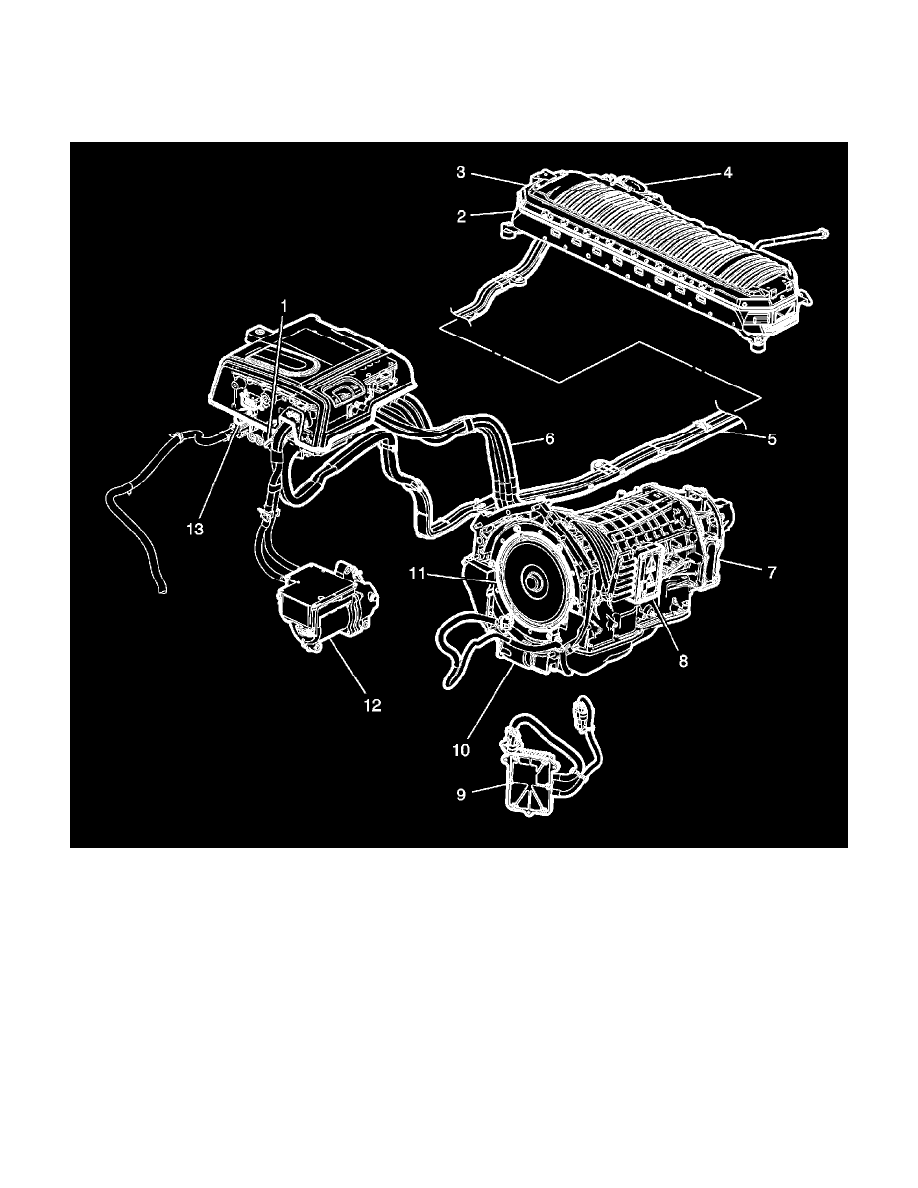
Front of Vehicle/Engine Compartment Component Views
Hybrid Control Electronic Component Views (HP2)
1 - Accessory DC Power Control Module
2 - Drive Motor Generator Battery
3 - Drive Motor Generator Battery Control Module
4 - Drive Motor Battery Cable Terminal Extension Cover
5 - Drive Motor Battery 300 Volt Positive and Negative Cable Assembly
6 - Drive Motor Generator Power Inverter Module 3 Phase Cable Assembly
7 - Drive Motor with Generator Assembly - 2nd Position
8 - Transmission Power Inverter Module (3 Phase) Cable Cover
9 - Automatic Transmission Auxiliary Fluid Pump Control Module
10 - Automatic Transmission Auxiliary Fluid Pump
11 - Drive Motor with Generator Assembly - 1st Position
12 - A/C Compressor
13 - Drive Motor Generator Power Inverter Module