
Yukon Denali 4WD V8-6.0L Hybrid (2011)
Drink Holders: Testing and Inspection
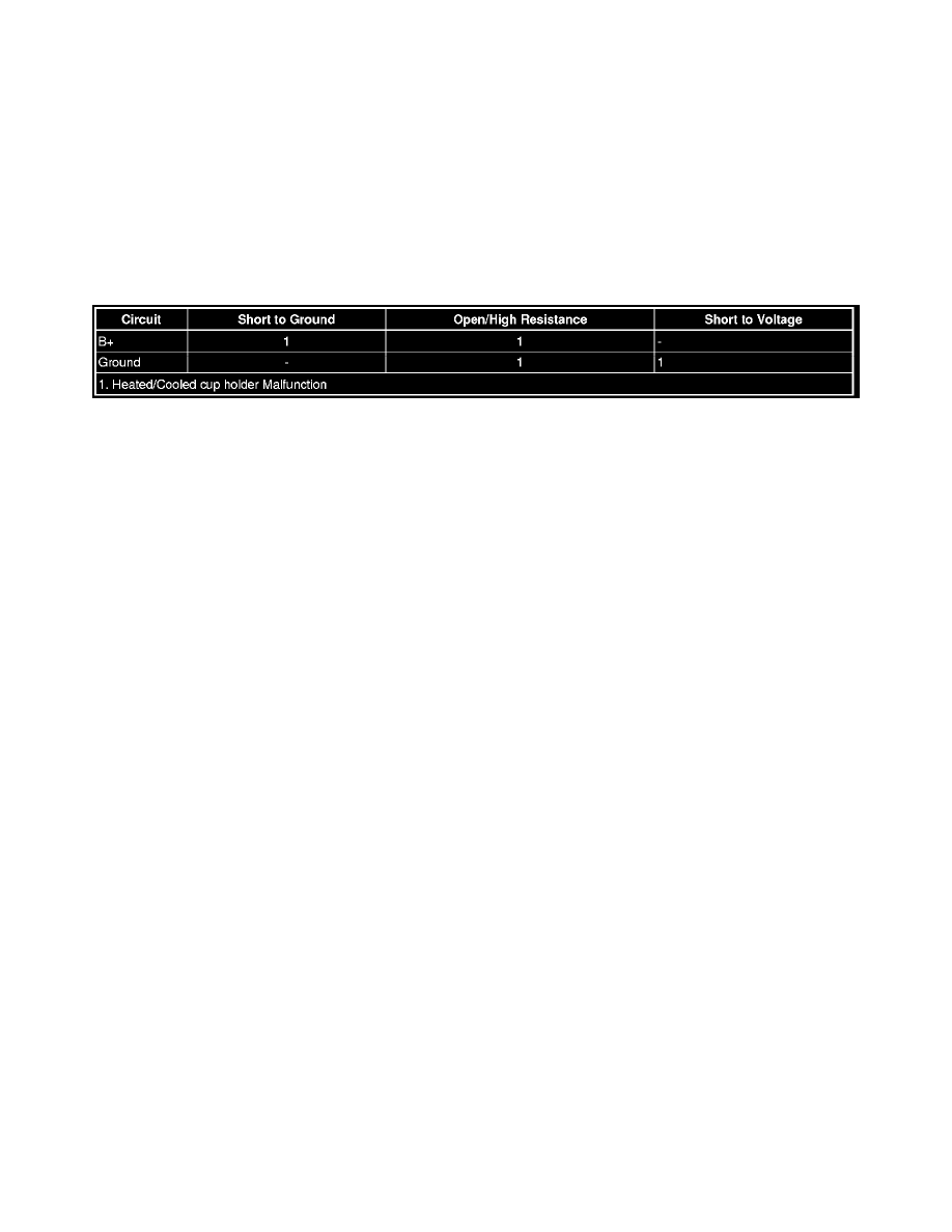
Heated/Cooled Cup Holder Malfunction
Diagnostic Instructions
*
Perform the Diagnostic System Check - Vehicle See: Testing and Inspection/Initial Inspection and Diagnostic Overview/Diagnostic System
Check - Vehicle prior to using this diagnostic procedure.
*
Review Strategy Based Diagnosis See: Testing and Inspection/Initial Inspection and Diagnostic Overview/Strategy Based Diagnosis for an
overview of the diagnostic approach.
*
Diagnostic Procedure Instructions See: Testing and Inspection/Initial Inspection and Diagnostic Overview/Diagnostic Procedure Instructions
provides an overview of each diagnostic category.
Diagnostic Fault Information
Circuit/System Description
The Heated/Cooled cup holder system uses a positive temperature coefficient (PTC) ceramic element. The PTC is attached to the side of an aluminum
cylinder that forms the cup holder to provide the temperature change. B+ will either heat or cool the PTC element in the cup holder. Voltage applied in
one direction heats the element and cools it when the polarity is reversed. A momentary switch on the console surface operates the unit. It offers off, heat
and cool settings. The cup holders have a temperature range that heats to 140°F or cools to 35°F. A light in the switch glows red to indicate heating and
blue to indicate cooling.
Reference Information
Schematic Reference
Heated/Cooled Cup Holder Schematics See: Diagrams/Electrical Diagrams
Connector End View Reference
Component Connector End Views See: Diagrams/Connector Views/Connector End Views By Name
Description and Operation
Heated/Cooled Cup Holder Description and Operation See: Description and Operation
Electrical Information Reference
*
Circuit Testing See: Testing and Inspection/Component Tests and General Diagnostics/Circuit Testing/Circuit Testing
*
Connector Repairs See: Testing and Inspection/Component Tests and General Diagnostics/Connector Repairs/Connector Repairs
*
Testing for Intermittent Conditions and Poor Connections See: Testing and Inspection/Component Tests and General Diagnostics/Circuit
Testing/Testing for Intermittent Conditions and Poor Connections
*
Wiring Repairs See: Testing and Inspection/Component Tests and General Diagnostics/Wiring Repairs/Wiring Repairs
Scan Tool Reference
Control Module References See: Testing and Inspection/Programming and Relearningfor scan tool information
Diagnostic Aids
If heating or cooling is insufficient make sure the air vents on either side of the console are not blocked in any way.
Circuit/System Verification
Ignition ON, turn the Heated/Cooled cup holder ON. Feel the inside of the Heated/Cooled cup holder it should feel warm or cool to the touch within a
few minutes depending on the switch position.
Circuit/System Testing
1. Ignition OFF, disconnect the harness connector at the Heated/Cooled cup holder.
2. Test for less than 10 ohms between the ground circuit terminal A and ground.