
Yukon XL 2500 4WD V8-6.0L VIN U (2005)
11. Snap the tumblers into place with light hand pressure.
12. Inspect for correct loading of the tumblers (4) by inserting the key into cylinder (7). All of the tumblers should be flush with the lock cylinder.
13. Lightly lubricate the tumblers (4) surfaces using the provided lubricant.
14. With the key inserted into the housing, align the retaining bar with the groove on the inside diameter of the cylinder housing. This groove extends
through to the back of the lock housing (6).
15. Lifting the flat spring and button, install the cylinder (7) into the cylinder housing (6). The retainer bar snaps into place when the cylinder (7) is
fully seated.
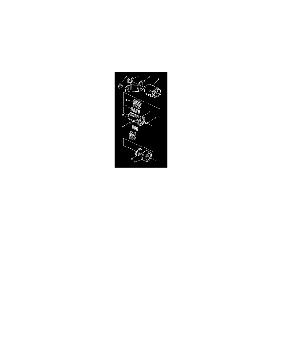
ASSEMBLING AND CODING DOOR LOCK CYLINDER
The door lock cylinder only uses seven of the ten cut positions, 3 through 9. The tumbler positions are staggered from side to side, 4 on one side and 3
on the other. The left and right door lock cylinders are identical. The lock pawl determines the side of the vehicle the lock cylinder is on.
1. Hold the cylinder (5) so that the side with the four tumbler spring wells faces up.
IMPORTANT: The door lock cylinder tumblers are not self-retaining. Hold the tumblers in place when the key is not in the lock cylinder. Hold the
lock tumblers (12) in place when performing the next steps.
2. Insert tumbler springs (11) into the four spring wells.
3. Install the tumbler for key cut position 3 in the slot nearest to the front of the lock cylinder.
4. Install the 3 remaining tumblers, key cut positions 5, 7 and 9, on this side of the lock cylinder.
5. Snap the tumblers into place with light hand pressure.
6. Check for correct loading of the tumblers (12) by inserting the key into the cylinder (5). All of the tumblers should be flush with the lock cylinder.
7. Turn the cylinder (5) so that the side with the 3 tumbler spring wells faces up.
8. Insert the tumbler springs (11) into the 3 spring wells.
9. Install the tumbler for key cut position 4 into the slot nearest the front of the lock cylinder.
10. Install the 2 remaining tumblers for key cut positions 6 and 8 on this side of the lock cylinder.
11. Snap the tumblers into place with light hand pressure.
12. Check for correct loading of the tumblers (12) by inserting the key into the cylinder (5). All of the tumblers should be flush with the lock cylinder.
13. Lightly lubricate the tumbler (12) surfaces using the provided lubricant.
14. Install the 2 plate springs (6) into the 2 spring wells in the head of the door lock cylinder (5).
15. Snap the shutter assembly (8) onto the cylinder.
16. Insert the key into the lock cylinder.
17. Place the detent spring (10) into the spring well located on the side of the lock cylinder (5).
18. Carefully place the detent ball (9) on the detent spring (10).
19. Depress the detent ball and spring and insert the cylinder (5) into the cylinder housing (4).
CAUTION: Wear safety glasses in order to avoid eye damage.
20. Install the lock pawl (3).
21. Install the lock pawl E-clip (2) to retain the lock pawl.
22. Remove the key from the lock cylinder (5).
23. Install the lock cylinder cap (7) by aligning the notch in the cap with the large drain slot in the lock housing (4).Press the cap into place with light
hand pressure.
ASSEMBLING AND CODING IP STORAGE COMPARTMENT LOCK CYLINDER
The IP storage compartment lock only uses 4 of the 10 cut positions 7 through 10. A retainer tumbler is used in the IP storage compartment lock to