
Yukon XL 4WD V8-5.3L (2011)
3. Release the terminal from the connector:
*
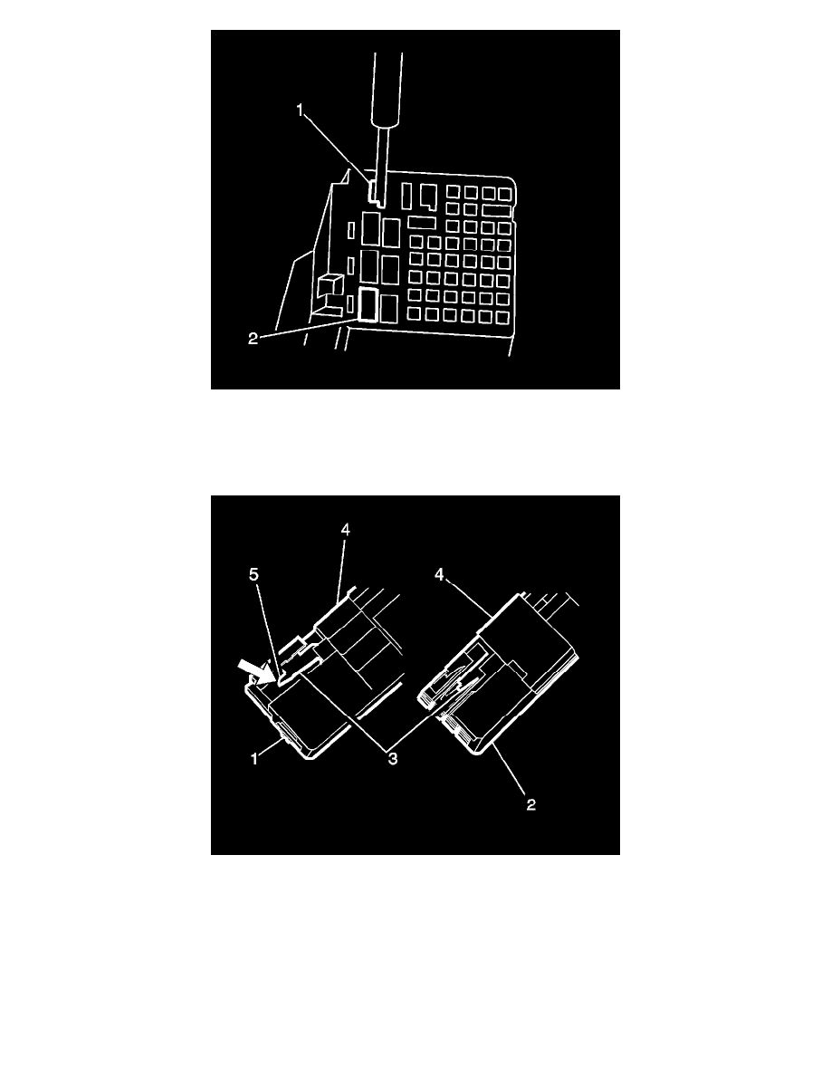
Position the connector as shown (above) and locate the terminal release entry canal (1) of the suspect terminal.
*
Insert the connector terminal release tool J-38125-553 into the entry canal with the angled side of the tool facing the connector wall containing
cavity 4 (2).
*
The cavity on the left (1) is a 2.8 mm cavity and the cavity on the right (2) is a 0.64 mm cavity.
*
Place the tip of the connector terminal release tool onto the connector lance (3) and deflect the lance to the right (5) to release the lock. Hold
this released position.
*
Holding the lance in the released position, slightly pull on the suspect terminal to remove it from the connector housing. The side TPA (4) is a
secondary lock.
4. Repair the terminal by following the Repairing Connector Terminals See: General Electrical Diagnostic Procedures/Connector Repairs/Repairing
Connector Terminals procedure.
5. Insert the repaired terminal back into the cavity. Repeat the diagnostic procedure to verify the repair and reconnect the connector bodies.
Kostal Connectors