
Accord L4-1955cc 2.0L SOHC 2-bbl (1986)
EGR Valve Lift Sensor: Testing and Inspection
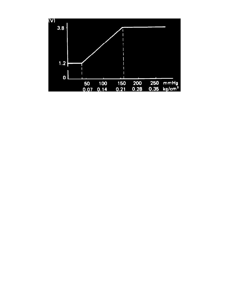
Fig. 66 EGR valve lift sensor test chart.
1.
Connect suitable system checker harness between ECU and wire harness coupler, then turn on ignition.
2.
Measure voltage between terminal C13 (red/blue (+)) and terminal C12 (green/white ( - )) of system checker harness.
3.
If 1.0-1.4 volts are present, substitute a known good ECU and retest EGR system and components. If EGR still is not satisfactory, replace original
ECU. If 1.0-1.4 volts are not present, proceed to step 4.
4.
Turn off ignition, then check for open or short circuit in terminals C12 and C13 between EGR valve lift sensor and ECU.
5.
If open or short is present, proceed to step 6. If open or short is not present, wire harness is faulty.
6.
Turn on ignition, then connect suitable hand vacuum pump to upper hose of the EGR valve.
7.
While applying vacuum, measure voltage between terminal C8 (red/blue (+)) and terminal C12 (green/white (-) of the system harness checker.
8.
If voltage is not as specified in Fig. 66, replace EGR valve lift sensor. If voltage is as specified in Fig. 66, substitute a known good ECU and retest
EGR system and components. If EGR is still not satisfactory, replace original ECU.