
Accord L4-2156cc 2.2L SOHC (1991)
Crankshaft Position Sensor: Description and Operation
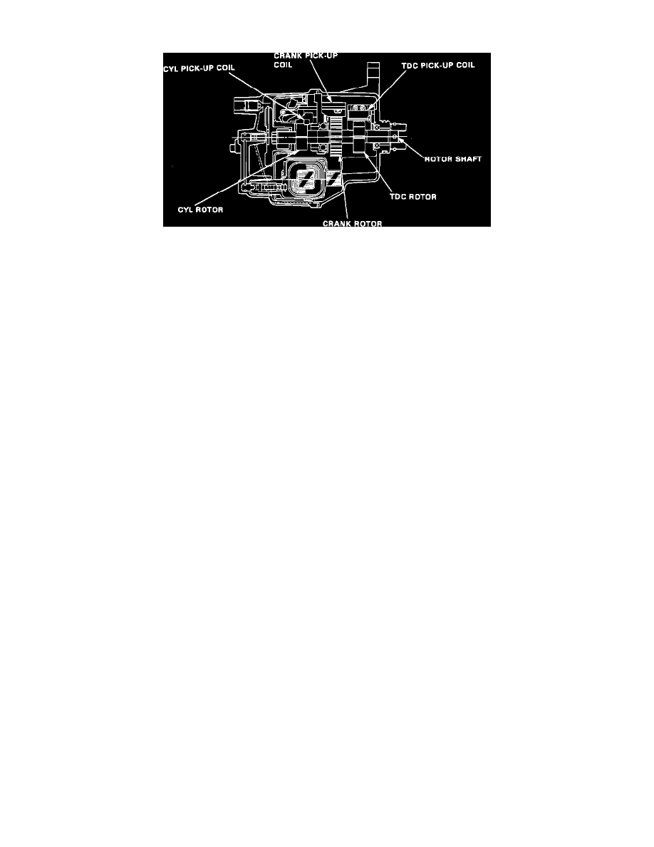
TDC/CRANK/CYL Sensor
This sensor, contained in the distributor housing, consists of three rotors, TDC, CRANK, and CYL, their associated pickup coils, and a common shaft.
Since the rotors are coupled to the cam shaft, they turn together as a unit as the cam shaft rotates. As the teeth of each rotor breaks the flux lines of their
respective pick-up coils a voltage pulse is generated. These pulses are the input signal to the ECU.
The CRANK sensor detects engine rpm and is a primary input to the ECU for determing timing for fuel injection and ignition of each cylinder. The
TDC sensor determines ignition timing at start-up (cranking) and when crank angle is abnormal. The CYL sensor detects the position of No. 1 cylinder
for sequential fuel injection to each cylinder.