
Accord L4-2156cc 2.2L SOHC (1991)
Shift Solenoid: Testing and Inspection
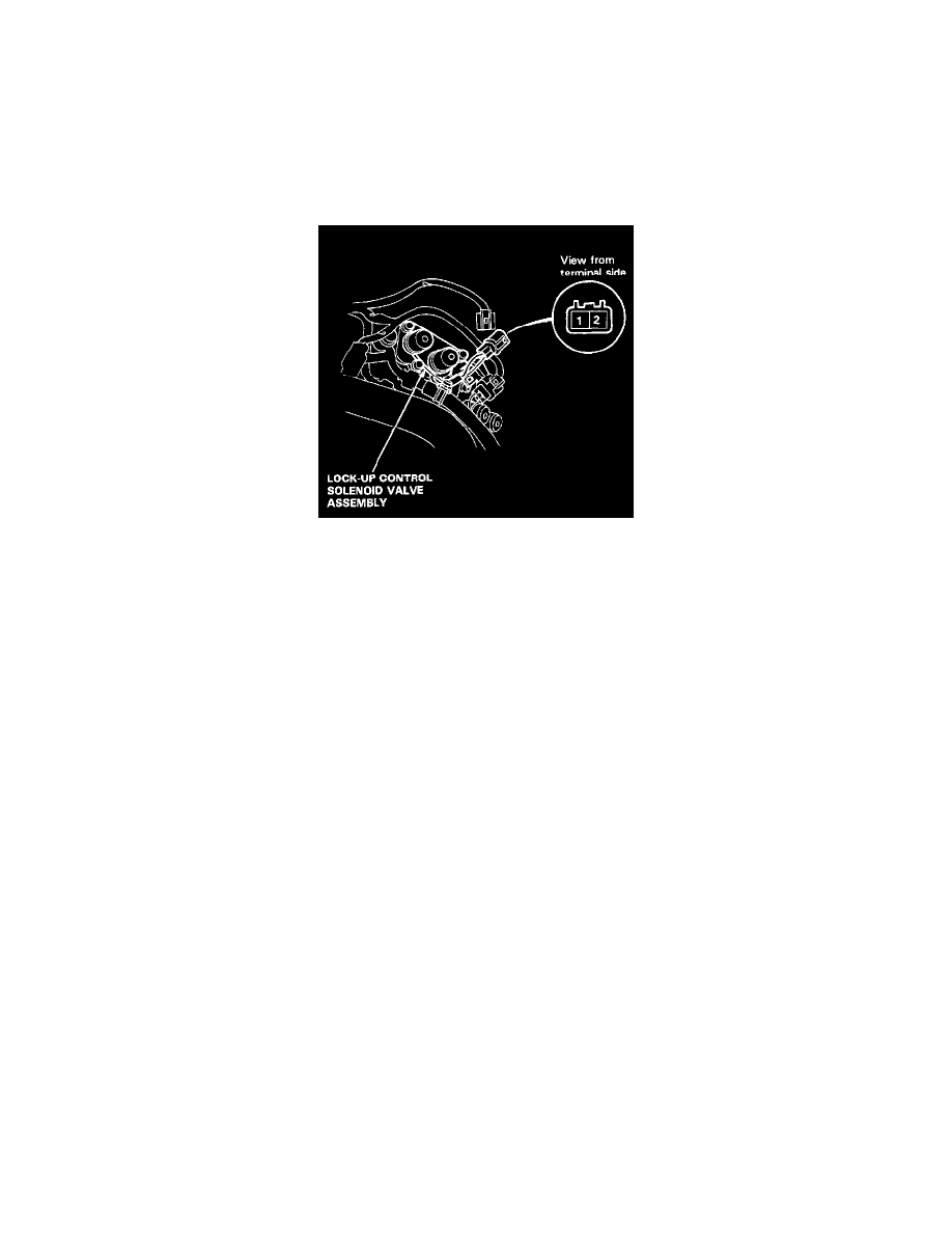
Lock-Up Solenoid Valve Test
LOCK-UP CONTROL SOLENOID VALVE A/B TEST
NOTE: Lock-up control solenoid valves A and B must be removed/replaced as an assembly.
1. Disconnect the connector from the lock-up control solenoid valve A/B.
NOTE: Do not remove the lock-up control solenoid valve A/B stay.
2. Measure the resistance between the No.1 terminal (SOL. V A) of the lock-up control solenoid valve connector and body ground and between the
No.2 terminal (SOL. V B) and body ground.
STANDARD: ....................................................................................................................................................................................... 12 - 24 Ohms
3. Replace the lock-up control solenoid valve assembly if the resistance is out of specification.
4. Connect the No. 1 terminal of the lock-up control solenoid valve connector to the battery positive terminal. A clicking sound should be heard.
Connect the No. 2 terminal to the battery positive terminal. A clicking sound should be head.
5. If not, check for continuity between the A/T control unit A4 or A6 harness and body ground. Refer to Trouble Code Diagnostic Charts / LED
Indicator Blinks Once. See: Transmission Control Systems/Testing and Inspection
6. Replace the lock-up control solenoid valve assembly if there is continuity between the A/T control unit A4 or A6 harness and body ground. Refer
to Trouble Code Diagnostic Charts / LED Indicator Blinks Once. See: Transmission Control Systems/Testing and Inspection