
Accord L4-2156cc 2.2L SOHC (1991)
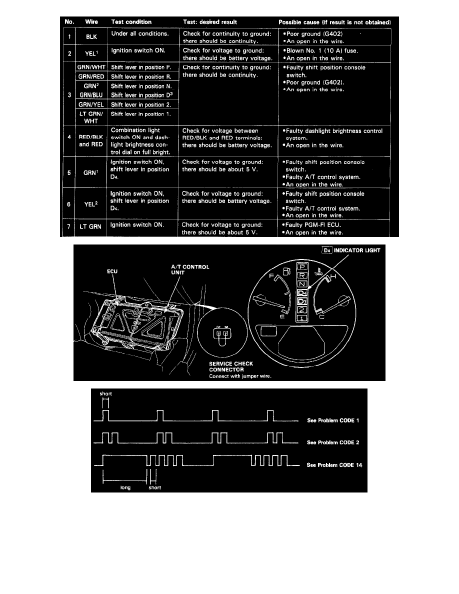
When the A/T control unit senses an abnormality in the input or output systems, the D4 indicator light in the gauge assembly will blink. However,
when the Service Check Connector (located to the lower right of the glove compartment) is connected with a jumper wire, the D4 indicator light will
blink the problem code when the ignition switch is turned on.
When the D4 indicator light has been reported on, connect the two terminals of the Service Check Connector together. The turn on the ignition switch
and observe either the D4 indicator light. Problem codes 1 through 9 are indicated by individual short blinks, Problem codes 10 through 15 are
indicated by a series of long and short blinks. One long blink equals 10 short blinks. Add the long and short blinks together to determine the problem
code. After determining the problem code, refer to the electrical system Symptom-to-Component Chart below.