
Accord V6-3.0L Hybrid (2005)
1. Place the digital volt/ohmmeter (DVOM) in the appropriate DC volts range. Connect the positive lead to the end of the wire (or to the connector or
switch) closest to the battery.
2. Connect the negative lead to the other end of the wire (or the other side of the connector or switch).
3. Turn on the components in the circuit.
4. The DVOM will show the difference in voltage between the two points. A difference, or drop, of more than one volt indicates a problem. Check
the circuit for loose, dirty, or bent terminals.
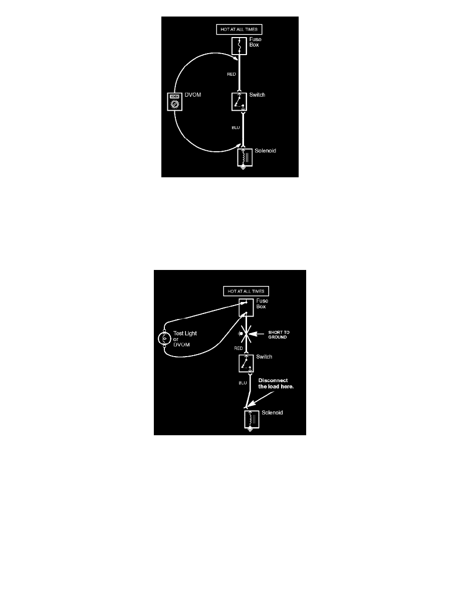
Testing for a Short with a Test Light or DVOM
1. Remove the blown fuse and disconnect the load.
2. Connect a test light or digital volt/ohmmeter (DVOM), switched to the appropriate DC volts range, across the fuse terminals to make sure voltage
is present. You might have to turn the ignition switch to ON; check the schematic to see.
3. Beginning near the fuse box, wiggle the harness. Continue this at convenient points about six inches apart while watching the test light or DVOM.
4. Where the test light goes off, or the DVOM voltage drops to zero, there is a short to ground in the wiring near that point.
NOTE: Always use a DVOM on high impedance circuits. A test light may not glow (even with battery voltage present).
How to Replace Connector Terminals
Terminal Replacement Procedure
HOW TO REPLACE CONNECTOR TERMINALS
The terminal repair kits provide necessary tools and materials (terminals, wire seals, and splice connectors) to repair many damaged or faulty connector
terminals. However, not all terminals for all connectors are available. Refer to the labels on the lids of the repair kits for replacement terminal
availability.