
Accord V6-3.0L Hybrid (2005)
Is there a repeating DTC?
YES - Count the blinks, then go to step 7.
NO - Go to step 8.
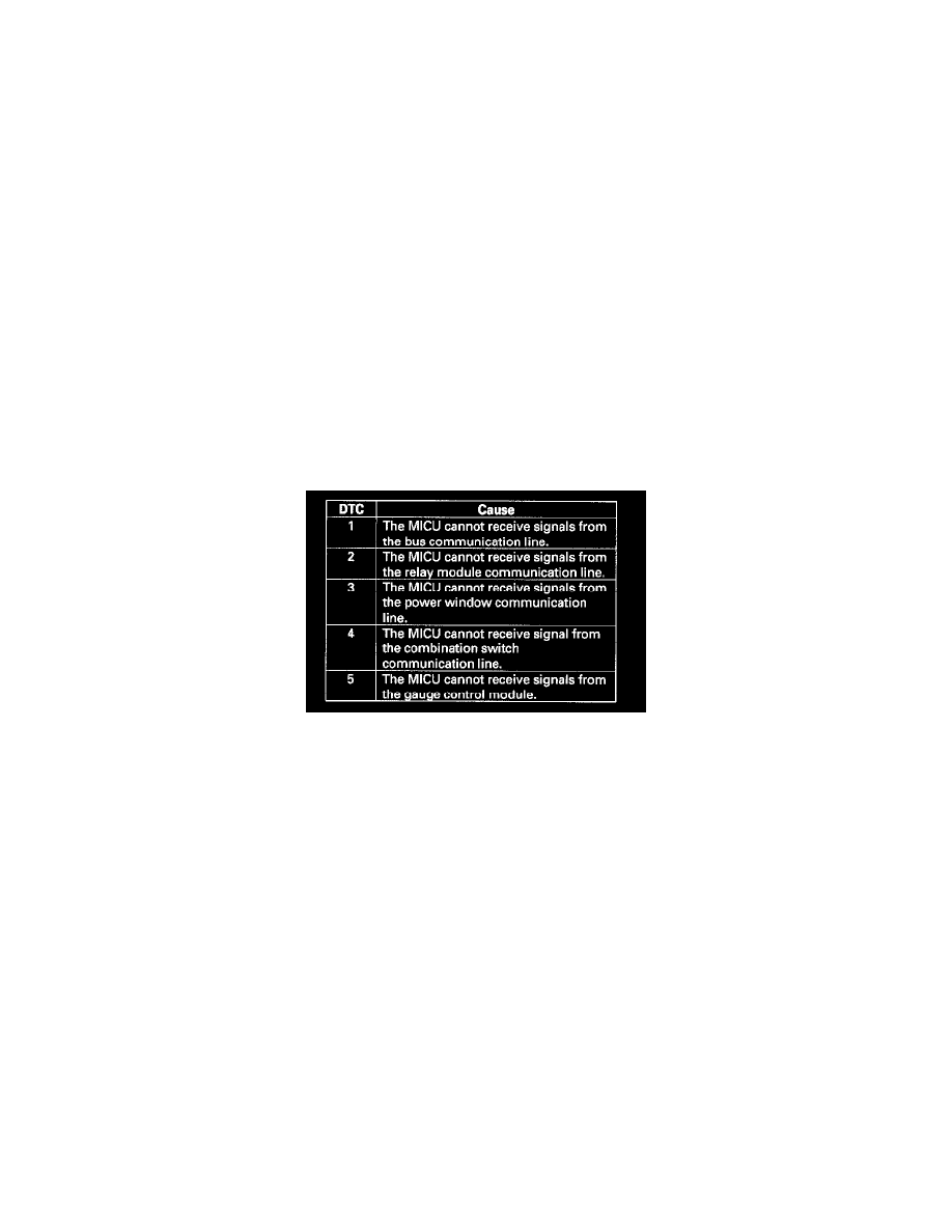
7. About 1 second after you go into self-diagnosis Mode 1, the ceiling light will indicate the DTC, and repeat it every 3 seconds. If there is more
than one DTC, the system will indicate them in ascending order, beginning from the DTC with the lowest numerical value. Troubleshoot the DTCs
as indicated below:
-
DTC 2,3, 4 and 5 simultaneously: Check for an open in the BLU wire between multiplex integrated control unitD11 and relay module 17,
BRN/RED wire between multiplex integrated control unit J4 and door multiplex control unit No. 16, LT GRN wire between multiplex
integrated control unit X27 and combination switch control unit No. 4, BRN/YEL wire between multiplex integrated control unit N28 and
gauge control module terminal No. 25. If the wire is OK, substitute a known-good under-dash fuse/relay box (multiplex integrated control
unit), under-hood fuse/relay box, power window master switch, wiper/washer switch and gauge one at a time, in that order, and recheck for the
DTCs after each substitution.
-
DTC 1 only: Go to MICU input test.
-
DTC 2 only (no other DTCs present): Go to the relay module input test. If all inputs are OK, substitute a known-good relay module and then a
MICU, one at a time, and then check for DTCs. If a DTC recurs after a substitution, replace that unit.
-
DTC 3 only (no other DTCs present): Go to the door multiplex control unit input test. If all inputs are OK, substitute a known-good door
multiplex control unit and then a MICU, one at a time, and then check for DTCs. If a DTC recurs after a substitution, replace that unit.
-
DTC 4 only (no other DTCs present): Go to the combination switch control unit input test. If all inputs are OK, substitute a known-good
wiper/washer switch and then a MICU, one at a time, and then check for DTCs. If a DTC recurs after a substitution, replace that unit.
-
DTC 5 only (no other DTCs present): Go to the gauge control module input test. If all inputs are OK, substitute a known-good gauge control
module and then a MICU, one at a time, and then check for DTCs. If a DTC recurs after a substitution, replace that unit.
8. Check for B-CAN DTCs indicated by the gauge control module while still in Test Mode 1.
Are any DTCs indicated?
YES - Go to step 9.
NO - Go to step 11.
9. Record all DTCs and sort them by type using the DTC Troubleshooting.
10. Troubleshoot the DTCs in the following order:
-
Battery voltage DTCs
-
Internal error DTCs
-
Loss of communication DTCs (begin with the lowest number first; for example, if B1006 and B1059 are retrieved, troubleshoot B1006 first)
-
Signal error DTCs
11. Remove the MPCS service connector from the under-dash fuse/relay box socket for 5-10 seconds, then re-insert it.
NOTE: If the MPCS connector is disconnected for too short or too long of a time, or the ignition switch is turned OFF, the system will return to
Test Mode 2.