
Accord Coupe L4-2.2L SOHC VTEC (1995)
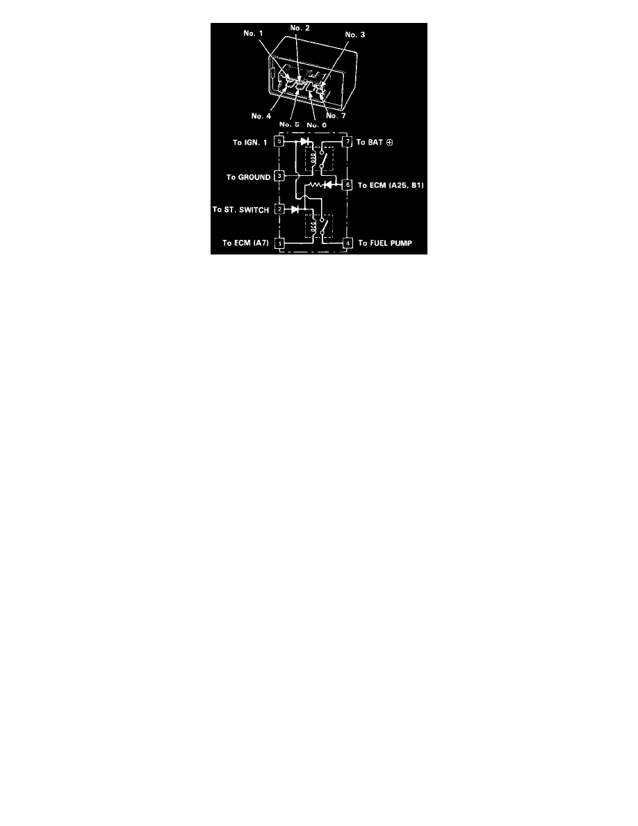
PGM-FI Main Relay Terminals
2. Attach the battery positive terminal to the No. 2 terminal and the battery negative terminal to the No. 1 terminal of the PGM-FI main relay. Then
check for continuity between the No. 5 terminal and No. 4 terminal of the PGM-FI main relay.
^
If there is continuity, go on to step 3.
^
If there is no continuity, replace the PGM-FI main relay and retest.
3. Attach the battery positive terminal to the No. 5 terminal and the battery negative terminal to the No. 3 terminal of the PGM-FI main relay. Then
check that there is continuity between the No. 7 terminal and No.6 terminal of the PGM-FI main relay.
^
If there is continuity, go on to step 4.
^
If there is no continuity, replace the PGM-FI main relay and retest.
4. Attach the battery positive terminal to the No. 6 terminal and the battery negative terminal to the No. 1 terminal of the PGM-FI main relay. Then
check that there is continuity between the No. 5 terminal and No. 4 terminal of the PGM-FI main relay.
^
If there is continuity, the PGM-FI main relay is OK.
^
If there is no continuity, replace the PGM-FI main relay and retest.