
Accord Coupe L4-2.2L SOHC VTEC (1995)
Lock-Up Control Solenoid Valve A/B: Testing and Inspection
NOTE: Lock-up Control Solenoid Valves A and B must be removed or replaced as an assembly.
1. Disconnect the Connector from the Lock-up Control Solenoid Valve A/B.
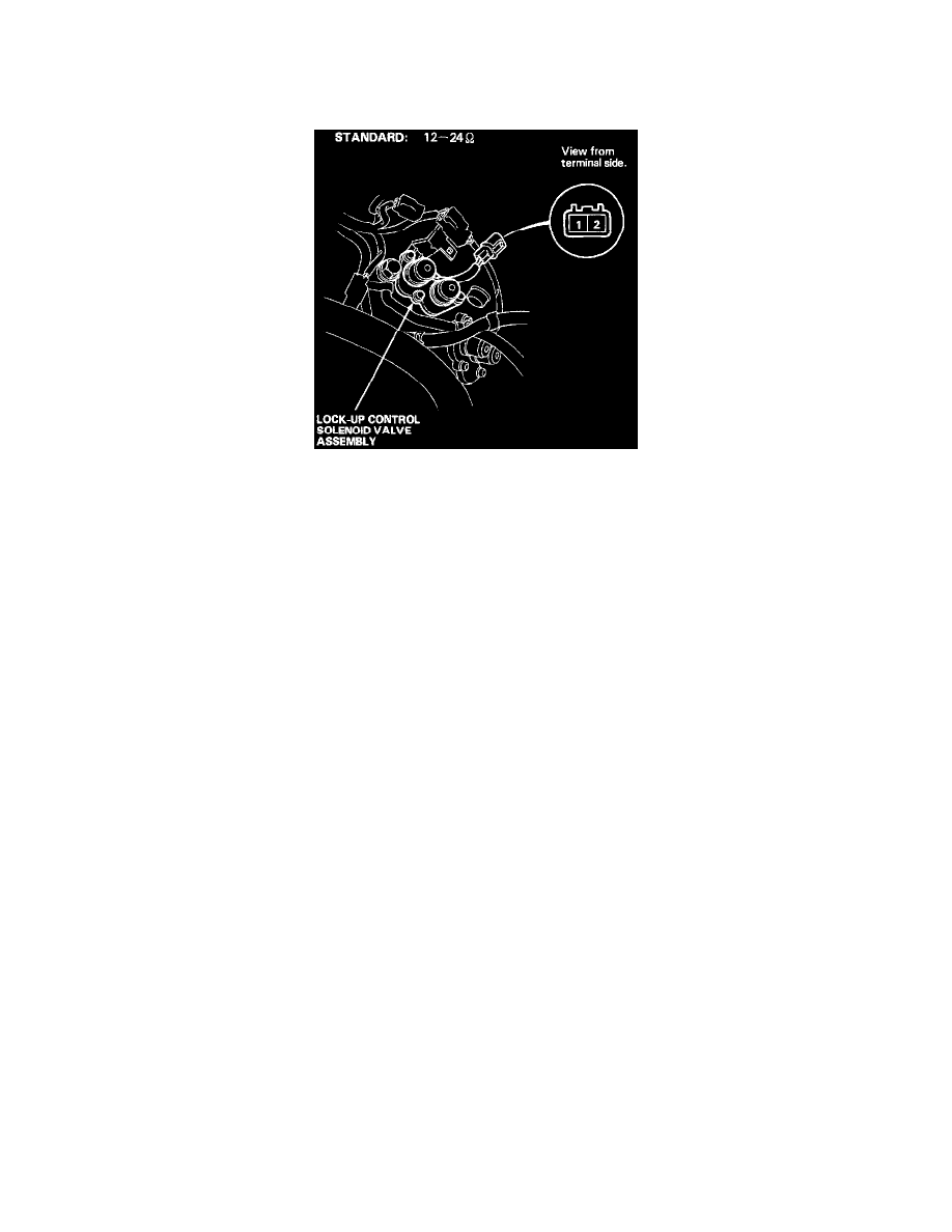
2. Measure the resistance between the No. 1 Terminal (Solenoid Valve A) of the Lock-up Control Solenoid Valve Connector and Body Ground, and
between the No. 2 Terminal (Solenoid Valve B) and Body Ground.
Resistance: ........................................................................................................................................................................................... 12 - 24 Ohms
3. Replace the Lock-up Control Solenoid Valve assembly if the resistance is out of specification.
4. If the resistance is within the standard, connect the No. 1 Terminal of the Lock-up Control Solenoid Valve Connector to the Battery Positive
Terminal. A clicking sound should be heard. Connect the No. 2 Terminal to the Battery Positive Terminal. A clicking sound should be heard.
Replace the Lock-up Control Solenoid Valve assembly if no clicking sound is heard.