
Accord SE Coupe L4-2156cc 2.2L SOHC MFI (1997)
Connector Pin Color And Function Chart
CAUTION:
^ All SRS wire harnesses are covered with yellow insulation. Before you disconnect any part of an SRS wire harness, disconnect the airbag
connectors.
^ Whenever the ignition switch ON (II), or has been turned OFF for less than three minutes, be careful not to bump the SRS unit; the airbags could
accidentally deploy and cause damage or injuries.
^ For additional precautions, refer to Air Bags and Seat Belts.
1. Remove the gauge assembly, and disconnect all connectors from it.
2. Inspect the connector and socket terminals to be sure they are all making good contact.
^ If the terminals are bent, loose or corroded, repair them as necessary, and recheck the system.
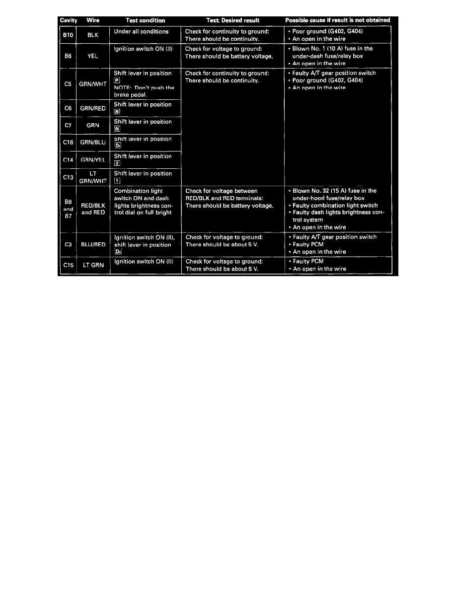
^ If the terminals look OK, make the following input tests at the 22-P (C6O9) and 16-P (C6O7) connectors.
-
If a test indicates a problem, find and correct the cause, then recheck the system.
-
If all the input tests prove OK, but the indicator is faulty, replace the printed circuit board A.