
Civic L4-1.3L Hybrid (2008)
Is there battery voltage while the brake pedal is pressed, and about 0 V when the pedal is released?
YES - Go to step 21.
NO - Go to step 20.
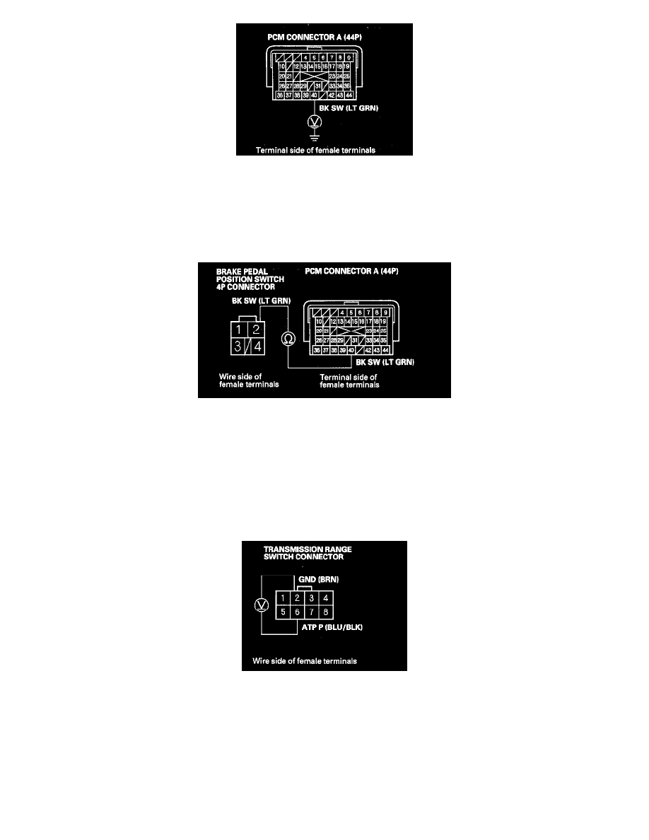
20. Check for continuity between PCM connector terminal A40 and brake pedal position switch 4P connector terminal No. 2.
Is there continuity?
YES - Substitute a known-good PCM, and recheck.
NO - Repair open in the wire between PCM connector terminal A40 and the brake pedal position switch.
21. Connect PCM connector A (44P).
22. Disconnect the transmission range switch connector.
23. Turn the ignition switch to ON (II).
24. Measure the voltage between transmission range switch connector terminals No. 2 and No. 6.
Is there about 5 V?
YES - Go to step 30.
NO - Go to step 25.
25. Turn the ignition switch to LOCK (0).
26. Disconnect PCM connector B (44P).
27. Check for continuity between PCM connector terminal B13 and body ground.