
Civic L4-1.8L (2006)
Information Bus: Initial Inspection and Diagnostic Overview
General Troubleshooting Information
General Troubleshooting Information
Troubleshooting CAN Circuit Related Problems
NOTE: Check the ECM/PCM for DTCs and troubleshoot ECM/PCM or F-CAN loss of communication errors first.
Using the HDS (Preferred method)
1. Go to B-CAN System Diagnosis Test Mode A to check for "Connected units" and DTCs. See: Component Tests and General
Diagnostics/Troubleshooting - B-CAN System Diagnosis Test Mode A
2. If no DTCs are retrieved, go to B-CAN System Diagnosis Test Mode C or D. See: Component Tests and General Diagnostics/Troubleshooting -
B-CAN System Diagnosis Test Mode C
Without HDS (Use only if the HDS is unavailable)
1. Check for communication circuit problems using B-CAN System Diagnostic Test.
2. Check for DTCs.
3. Sort, and then troubleshoot the DTCs in the order below.
1. Battery voltage DTCs
2. Internal error DTCs
3. Loss of communication DTCs (beginning with the lowest number first; for example, if B1008 and B1011 are retrieved, troubleshoot B1008
first)
4. Signal error DTCs
4. If no DTCs are retrieved, use B-CAN System Diagnostic Test Mode 2 to check all inputs related to failure.
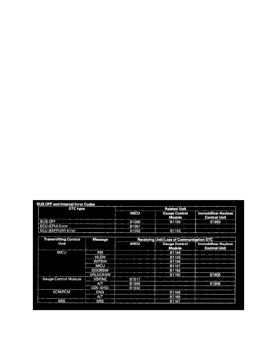
Loss of Communication DTC cross-reference chart
When an ECU is unable to communicate with the other ECUs on the CAN circuit, the other control units will set loss of communication DTCs. Use this
chart to find the control unit that is not communicating.
1. Find the Transmitting Control Unit that is in the same row as all of the loss of communication DTCs retrieved.
2. Do the input test for the transmitting control unit.
System Description
System Description