
Civic L4-1.8L (2006)
-
Horn (security and panic)
-
Wiper/washer
If the problem is related to one of the foil owing items, go to the troubleshooting for that individual system.
-
Gauge control module
-
Door-open and trunk-open indicators
-
Chimes (key-in, seat belt, lights-on, and parking brake)
-
Security
-
Keyless entry
-
Key interlock
-
Dash light brightness
-
Audio system
-
Navigation (if equipped)
5. Record all DTCs, and sort then by DTC type.
6. Troubleshoot the DTC(s) in this order:
-
Battery voltage DTCs.
-
Internal error DTCs.
-
Loss of communication DTCs. Begin troubleshooting with the lowest number first (Example: if DTC B1008 and B1011 are retrieved, begin by
troubleshooting B1008).
-
Signal error DTCs.
Troubleshooting - B-CAN System Diagnosis Test Mode B
Troubleshooting - B-CAN System Diagnosis Test Mode B
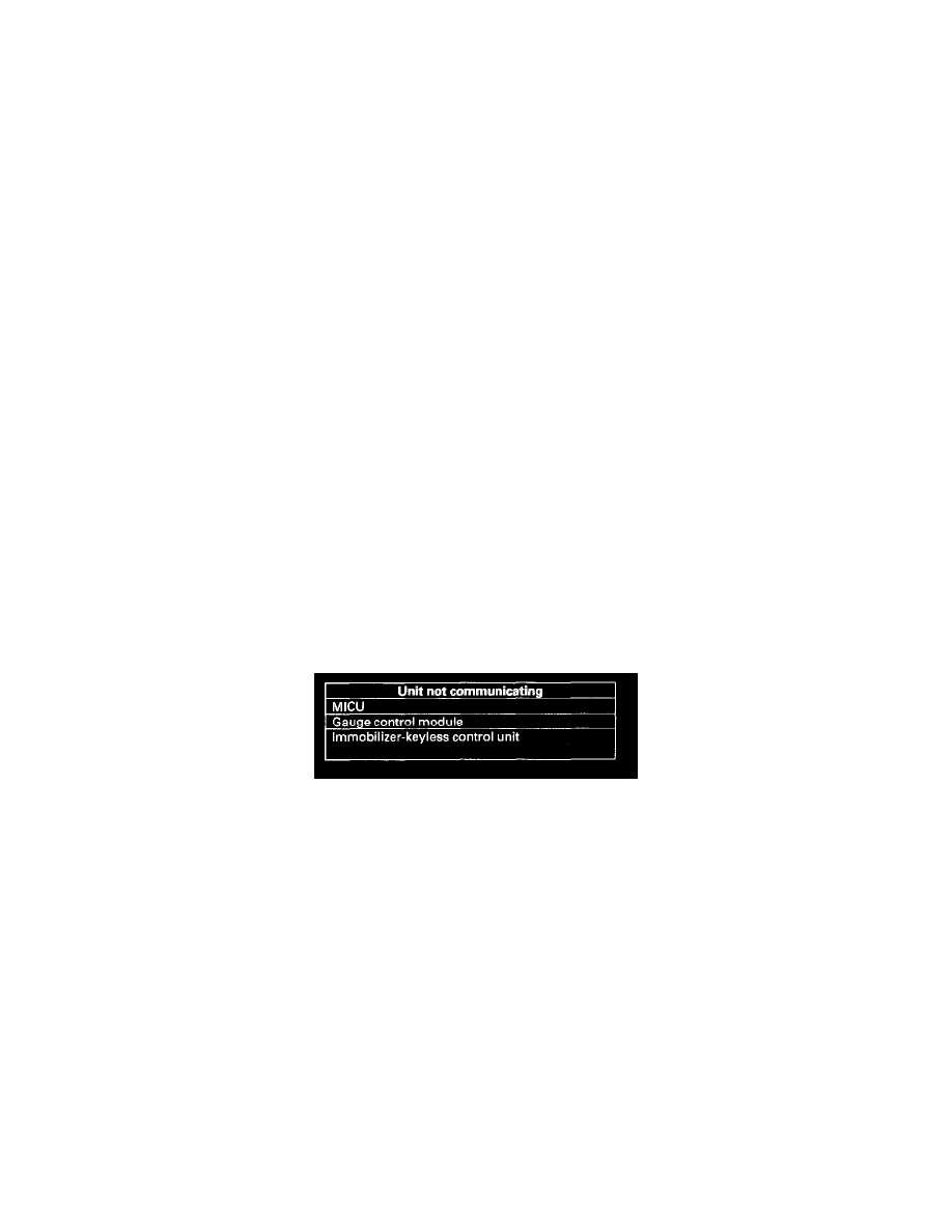
Perform this diagnosis if any of the control units are not communicating (Not Available is displayed in the HDS) as found by the B-CAN System
Diagnosis Test Mode A.
1. Using the HDS, select the system that has the symptom from the BODY ELECTRICAL menu.
2. Select DTCs, and then check for loss of communication DTCs.
Are any loss of communication DTCs indicated?
YES - Go to step 3.
NO - Replace the MICU.
3. Perform the input test for the unit not communicating with the HDS.
Troubleshooting - B-CAN System Diagnosis Test Mode C
Troubleshooting - B-CAN System Diagnosis Test Mode C
Perform this diagnosis if a component that is controlled by the B-CAN system does not stop or turn off.
NOTE:
-
If the component does not turn on, go to B-CAN System Diagnosis Test Mode D.
-
See the B-CAN system unit input/output index for a list of input and output devices and the control units that monitor the input and controls the
output devices.
-
Always cycle the ignition switch within 3 seconds when prompted in the DTC troubleshooting procedures in this section.
1. Check for DTCs by selecting the TEST MODE menu from the HDS.
Are any DTCs indicated?
YES - Go to B-CAN System Diagnosis Test Mode A.
NO - Go to step 2.
2. Turn off the switch that controls the malfunctioning component.
3. Select DATA LIST from the TEST MODE menu, and check the input of the switch that controls the component.