
Civic L4-1.8L (2006)
2. Remove the left kick panel.
-
4 door
-
2 door
3. Turn the ignition switch ON (II), and move the ceiling light switch to the middle (door) position.
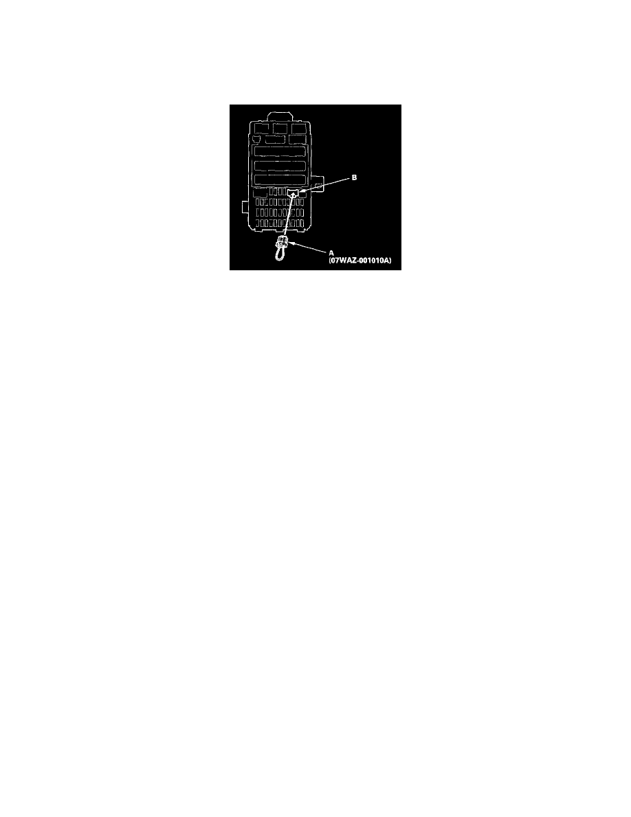
4. Connect the MFCS service connector (A) to the MCIC socket (B) in the under-dash fuse/relay box.
5. Wait 5 seconds, and watch the ceiling light. When the ceiling light flashes quickly once, and then goes off the system is in Test Mode 1.
6. Check for B-CAN DTCs indicated by the gauge control module (tach) odometer/trip meter display while still in Test Mode 1. Push the odometer
select/reset button to display the next code. After you get to the last code, the display shows END. If no DTCs are stored, the display will read NO.
Are any DTCs indicated?
YES - Go to step 7.
NO - Go to step 10.
7. Record all DTCs and sort them.
8. Troubleshoot the DTCs in this order:
-
Battery voltage DTCs
-
Internal error DTCs
-
Loss of communication DTCs (begin with the lowest number first; for example, if B1008 and B1011 are retrieved, troubleshoot B1008 first)
-
Signal error DTCs
9. Clear the DTCs by pressing and holding the select/reset button for about 13 seconds. You will hear a beep to confirm the code have been cleared.
Operate the devices that failed, and recheck for codes.
Test Mode 2
10. Remove the MFCS service connector from the under-dash fuse/relay box socket for 5-10 seconds, then re-insert it to enter Mode 2. When the
system enters Mode 2, the ceiling light will flash two times quickly and then go off.
NOTE: If the MFCS connector is disconnected for too short or too long of a time, or the ignition switch is turned OFF, the system will return to
Test Mode 1.