
Civic GX Sedan L4-1.6L CNG (1998)
component names are PHOTO and VIEW numbers. The PHOTO number refers to a photo that shows the connector's location on the car. The VIEW
number refers to an illustration that shows the connector face, wire colors, connector cavity numbers, and other details. The connector cavity numbering
sequence begins at the top left corner of the connector. Disregard any numbers molded into the connector housing. . Disregard any numbers molded into
the connector housing.. Disregard any numbers molded into the connector housing.
Wires
Wires are identified by the abbreviated names of their colors; the second color is the color of the stripe. Wires are also identified by their location in a
connector. The number "2" next to the male and female wire terminals at C416, for example, means those terminals join in cavity 2 of connector C416.
Symbols
A complete description of schematic symbols is given in wire color abbreviations.
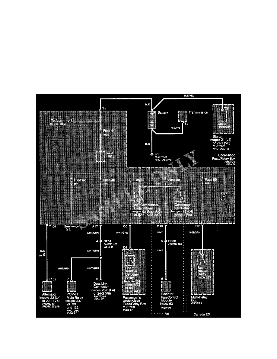
Power Distribution Schematics
Power Distribution schematics show how power is supplied from the positive battery terminal to various circuits in the car. Refer to the Power
Distribution to get a more detailed picture of how power is supplied to the circuit you're working on. Individual circuit schematics begin with a fuse. So
if Power Distribution shows that an inoperative circuit and another circuit share a fuse, check a component in the other circuit. If it works, you know the
fuse is good and power is available to the inoperative circuit.