
CR-V LX 2WD L4-1972cc 2.0L DOHC MFI (1998)
Shift Control Solenoid Valve: Testing and Inspection
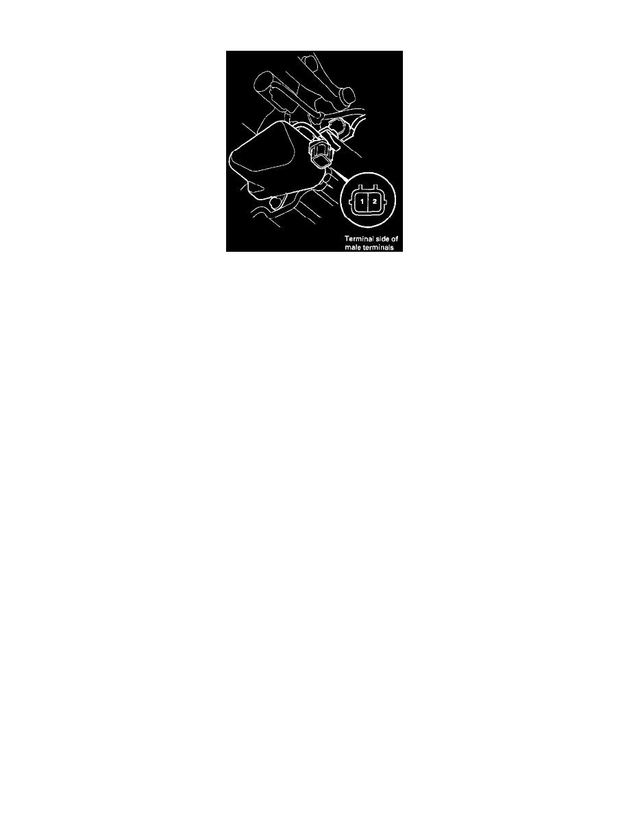
1. Disconnect the 2P connector from the shift control solenoid valve A/B assembly.
2. Measure the resistance between the No. 1 terminal (solenoid valve A) of the shift control solenoid valve connector and body ground and between
the No. 2 terminal (solenoid valve B) and body ground.
STANDARD: 12 - 25 ohms
3. Replace the shift control solenoid valve A/B assembly if the resistance is out of specification.
4. If the resistance is within the standard, connect the No. 1 terminal of the shift control solenoid valve connector to the battery positive terminal. A
clicking sound should be heard. Connect the No. 2 terminal to the battery positive terminal. A clicking sound should be heard. Replace the shift
control solenoid valve A/B assembly if no clicking sound is heard when either terminal is connected to the battery positive terminal.