
CR-V LX 4WD L4-2.4L (2002)
Oil Pressure Warning Lamp/Indicator: Diagnostic Aids
Five-Step Troubleshooting
Five-Step Troubleshooting
1. Verify The Complaint
Turn on all the components in the problem circuit to check the accuracy of the customer complaint. Note the symptoms. Do not begin disassembly
or testing until you have narrowed down the problem area.
2. Analyze The Schematic
Look up the schematic for the problem circuit. Determine how the circuit is supposed to work by tracing the current paths from the power source
through the circuit components to ground. Also, trace circuits that share wiring with the problem circuit. The names of circuits that share the same
fuse, ground, or switch, and so on, are referred to in each circuit schematic. Try to operate any shared circuits you didn't check in step 1. If the
shared circuits work, the shared wiring is OK, and the cause must be in the wiring used only by the problem circuit. If several circuits fail at the
same time, the fuse or ground is a likely cause.
Based on the symptoms and your understanding of the circuit's operation, identify one or more possible causes.
3. Isolate The Problem By Testing The Circuit
Make circuit tests to check the diagnosis you made in step 2. keep in mind that a logical, simple procedure is the key to efficient troubleshooting.
Test for the most likely cause of failure first. Try to make tests at points that are easily accessible.
4. Fix The Problem
Once the specific problem is identified, make the repair. Be sure to use proper tools and safe procedures.
5. Make Sure The Circuit Works
Turn on all components in the repaired circuit in all modes to make sure you've fixed the entire problem. If the problem was a blown fuse, be sure
to test all of the circuits on that fuse. Make sure no new problems turn up and the original problem does not recur.
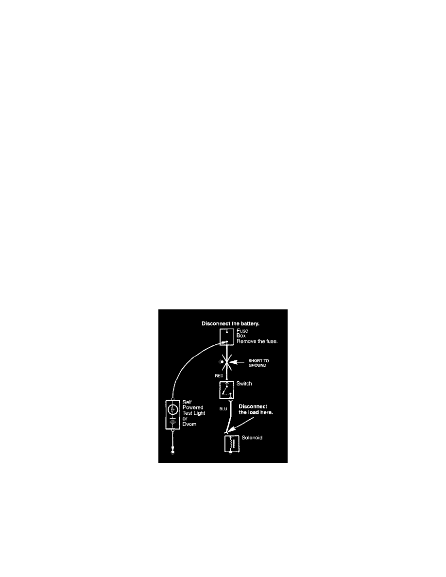
Testing For A Short With A Self-Powered Test Light or DVOM
Testing for a Short with a Self-Powered Test Light or DVOM
1. Remove the blown fuse and disconnect the battery and load.
2. Connect one lead of a self-powered test light or digital volt/ohmmeter (DVOM) (switched to the lowest "OHMS" range) to the fuse terminal on the
load side.
3. Connect the other lead to a known good ground.
4. Beginning near the fuse box, wiggle the harness. Continue this at convenient points about six inches apart while watching the test light or DVOM.
5. If the self-powered test light goes on or the DVOM displays a low reading or no reading (zero), there is a short to ground in the wiring near that
point.
Testing for a Short with a Test Light or DVOM
Testing for a Short with a Test Light or DVOM