
CR-V LX 4WD L4-2.4L (2002)
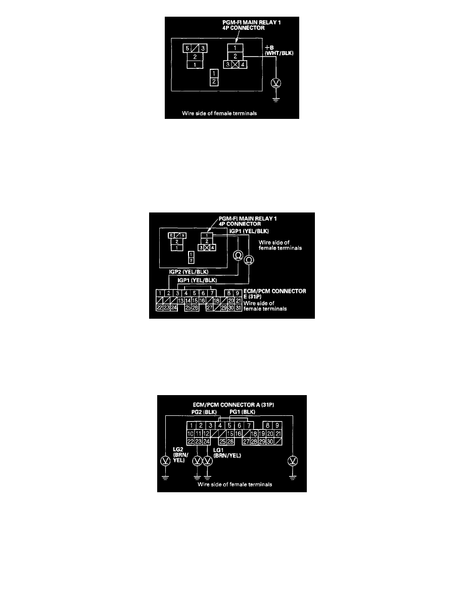
48. Measure voltage between PGM-FI main relay 1 4P connector terminal No. 2 and body ground.
Is there battery voltage?
YES - Go to step 49.
NO - Repair open in the wire between the No. 6 ECU (ECM/PCM) (15 A) fuse and PGM-FI main relay 1.
49. Turn the ignition switch OFF.
50. Check for continuity between PGM-FI main relay 1 4P connector terminal No. 1 and ECM/PCM connector terminals A2 and A3 individually.
Is there continuity?
YES - Replace PGM-FI main relay 1.
NO - Repair open in the wire between PGM-FI main relay 1 and the ECM/PCM (A2, A3).
51. Measure voltage between body ground and ECM/PCM connector terminals A4, A5, A23, and A24 individually.
Is there more than 0.2 V?
YES - Go to step 52.
NO - Repair open in the wire(s) that had more than 0.2 V between G101 and the ECM/PCM (A4, A5, A23, A24).