
CR-V SE 4WD L4-1972cc 2.0L DOHC MFI (2001)
Component connectors are not numbered but are identified either by the name of the component if the component only has one connector or by a capital
letter (A, B, C, etc.) it the component has more than one connector. Below most connector numbers and component names are PHOTO and VIEW
numbers. The PHOTO number refers to a photo in the back of the book that shows the connector's location on the car. The VIEW number refers to an
illustration in the back of the book that shows the connector face, wire colors, connector cavity numbers, and other details. The connector cavity
numbering sequence begins at the top left corner of the connector as seen from either of the viewpoints shown on page [9]. Disregard any numbers
molded into the connector housing.
Wires
Wires are identified by the abbreviated names of their colors; the second color is the color of the stripe. Wires are also identified by their location in a
connector. The number "2" next to the male and female wire terminals at C416, for example, means those terminals join in cavity 2 of connector C416.
Symbols
A complete description of schematic symbols begins on page [8].
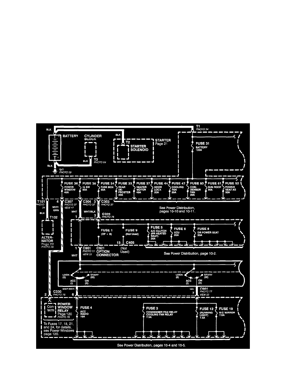
Power Distribution Schematics
Power Distribution schematics show how power is supplied from the positive battery terminal to various circuits in the car. Refer to the "Power
Distribution" to get a more detailed picture of how power is supplied to the circuit you're working on.