
Element 2WD L4-2.4L (2003)
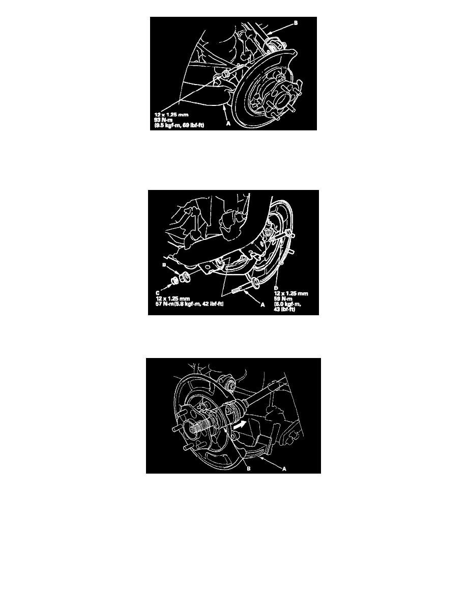
10. Place a floor jack under the trailing arm (A) to support it.
NOTE: Do not place the jack against the plate section of the lower arm. Be careful not to damage any suspension components.
11. Remove the flange bolt, and disconnect the upper arm (B) from the knuckle.
12. Mark the cam positions of the adjusting bolt (A) and adjusting cam (B), then remove the self-locking nut (C), adjusting cam, and adjusting bolt.
Discard the self-locking nut.
13. Remove the flange bolt (D).
14. Remove the knuckle (A) while pushing in the driveshaft and holding the driveshaft outboard joint (B) (4WD only).
15. Install the knuckle in the reverse order of removal, and note these items:
^
First install all the suspension components, and lightly tighten the bolts and nuts, then place a floor jack under the lower arm, and raise the
suspension to load it with the vehicle's weight before fully tightening the bolts and nuts to the specified torque values.
^
Align the cam positions of the adjusting bolt and adjusting cam with the marked positions when tightening.
^
Use a new self-locking nut on reassembly.
^
Use a new spindle nut on reassembly.
^
Before installing the spindle nut, apply a small amount of engine oil to the seating surface of the nut. After tightening, use a drift to stake the
spindle nut shoulder against the driveshaft.
^
Before installing the brake disc/drum, clean the mating surfaces of the rear hub and the inside of the brake disc/drum.
^
Before installing the wheel, clean the mating surfaces of the brake disc/drum and the inside of the wheel.
^
Check the rear wheel alignment, and adjust it if necessary.