
Fit L4-1.5L (2008)
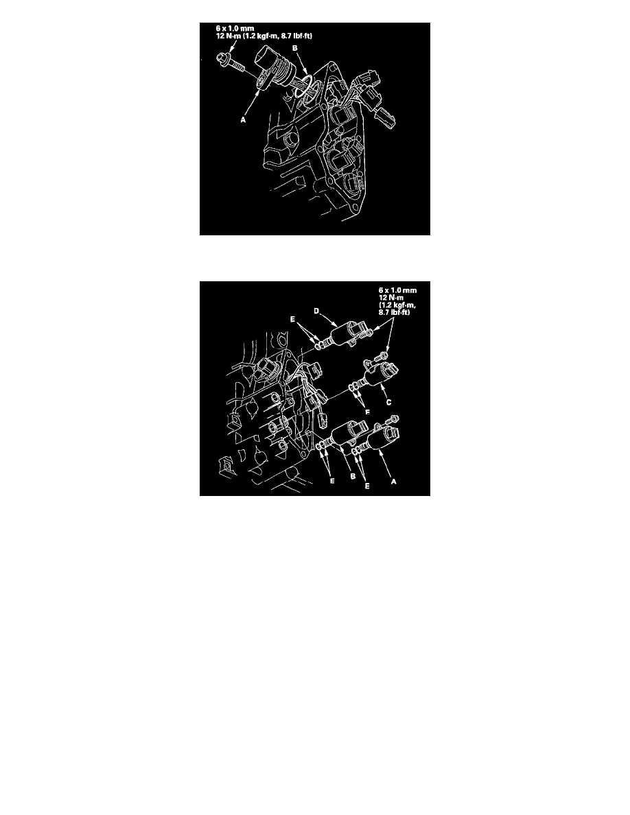
7. Remove the mounting bolts, then hold the solenoid valve body and remove the solenoid valves. Do not hold the connector to remove the solenoid
valve.
8. Install new O-rings (two O-rings per solenoid valve) (E) on the roused solenoid valve.
NOTE: A new solenoid valve comes with new O-rings. If you install a new solenoid valve, use the O-rings provided on it.
9. Install shift solenoid valve D (black connector) and shift solenoid valve C (brown connector) by holding the shift solenoid valve body; make sure
the mounting bracket contacts the servo body.
NOTE: Do not hold the solenoid valve connector to install the solenoid valve. Be sure to hold the solenoid valve body.
10. Install shift solenoid valve B (black connector) by holding the solenoid valve body; make sure the mounting bracket contacts the servo body.
11. Install shift solenoid valve A (brown connector) by holding the shift solenoid valve body; make sure the mounting bracket contacts the bracket of
shift solenoid valve B.
NOTE: Do not install shift solenoid valve A before installing shift solenoid valve B. If shift solenoid valve A is installed before installing shift
solenoid valve B, it may damage to hydraulic control system.
12. Connect the harness terminals to the solenoids:
^
BLU wire connector to shift solenoid valve A.
^
ORN wire connector to shift solenoid valve B.
^
GRN wire connector to shift solenoid valve C.
^
YEL wire connector to shift solenoid valve D.
13. Install the shift solenoid valve cover, dowel pins, and a new gasket.
14. Check the connector for rust, dirt, or oil, then connect the connector securely.