
Odyssey L4-2.2L SOHC (1995)
A broken border line indicates that only part of the component is shown.
Components
The name of the component appears next to its upper right corner followed by notes about its function.
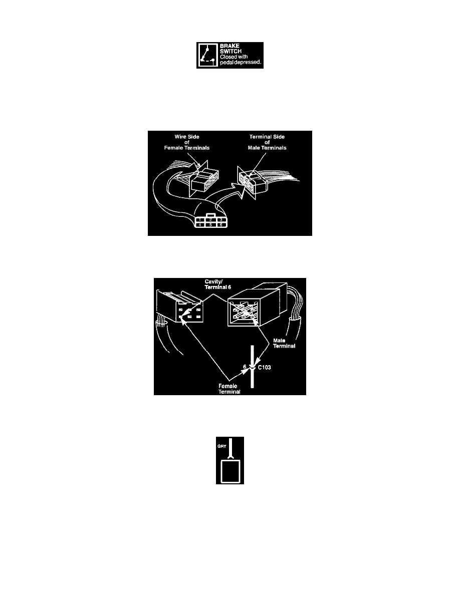
Connectors
The cavities (and wire terminals) in each connector are numbered starting from the upper left, looking at the male terminals from the terminal side (or
looking at the female terminals from the wire side. Both views are in the same direction so the numbers are the same.) All actual cavities are numbered,
even if they have no wire terminals in them.
Connectors-"C"
The connector cavity number is listed next to each terminal on the circuit schematic. The cavity/terminal shown here is #6.
Connectors-"C"
This means the connector connects directly to the component.