
Odyssey EX V6-3.5L (1999)
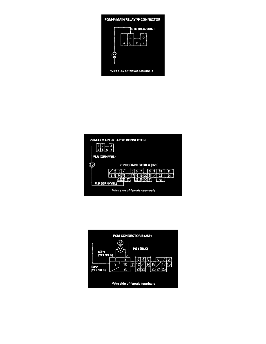
7. Shift to Park, then turn the ignition switch to the START (III) position, and measure voltage between body ground and the PGM-FI main relay 7P
connector terminal No.2.
Is there battery voltage?
YES - Go to step 9.
NO - Go to step 8.
8. Check for a blown No.13 STARTER SIGNAL (7.5 A) fuse in the driver's under-dash fuse/relay box.
Is the fuse blown?
YES - Repair the short in the wire between the PGM-FI main relay and the No. 13 STARTER SIGNAL (7.5 A) fuse.
NO - Repair the open in the wire between the PGM-FI main relay and the No.13 STARTER SIGNAL (7.5 A).
9. Turn the ignition switch OFF, and disconnect the PCM connector A (32P).
10. Check for continuity between the PGM-FI main relay 7P connector terminal No.1 and the PCM connector terminal A15.
Is there continuity?
YES - Go to step 11.
NO - Repair open in the wire between the PGM-FI main relay and the PCM (A15).
11. Reconnect the PCM connector A (32P) and the PGM-FI main relay 7P connector.
12. Turn the ignition switch ON (II), and measure voltage between the PCM connector terminals B1 and B2, and between B9 and B2.
Is there battery voltage?
YES - Go to step 13.
NO - Check for an open in the wires between the PGM-FI main relay and the PCM (B1, B9). If the wires are OK, replace the PGM-FI main relay.