
Odyssey EX V6-3.5L (1999)
Body Control Module: Diagram Information and Instructions
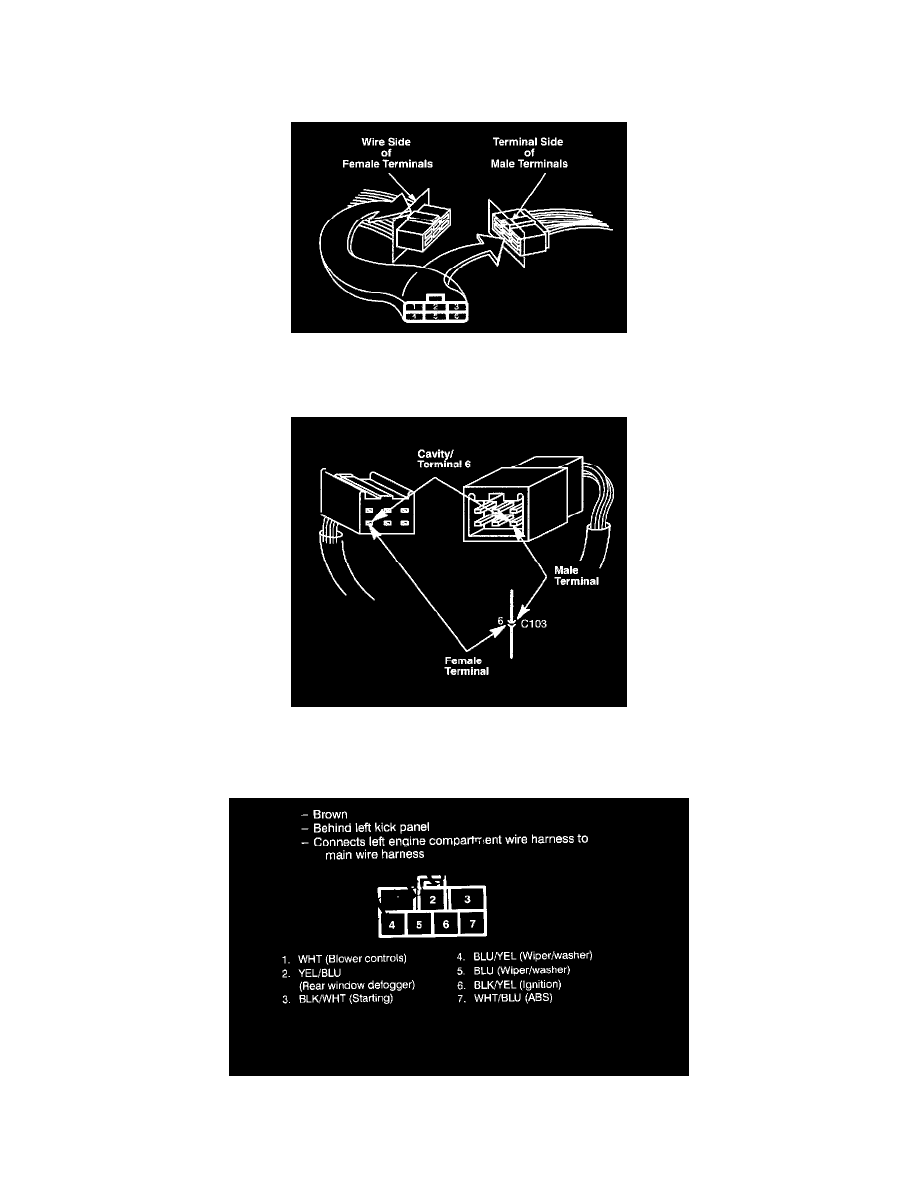
Cavity Numbering System
The cavities (and wire terminals) in each connector are numbered starting from the upper left, looking at the male terminals from the terminal side (or
looking at the female terminals from the wire side. Both views are in the same direction so the numbers are the same.) All actual cavities are numbered,
even if they have no wire terminals in them.
The connector cavity number is listed next to each terminal on the circuit schematic. The cavity/terminal shown is # 6.
Circuit Identification For In-Line and Fuse Box Connectors
To see the configuration of a connector's cavities, look up its view number in Cavity Numbering System. Each view includes the color of the connector,
where it is located, and what it connects to.