
Odyssey EX V6-3.5L (1999)
13. Turn the ignition switch OFF, then ON (II) again, and measure voltage between PCM connector terminals A15 and B2 within the first two
seconds after the ignition switch is turned ON (II).
Is there 1.0 V or less?
YES - PGM-FI main relay may be faulty: go to step 14.
NO - Substitute a known-good PCM and recheck. If prescribed voltage is now available, replace the original PCM.
See: Powertrain Management/Computers and Control Systems/Testing and Inspection/Initial Inspection and Diagnostic Overview/Diagnostic
Strategies
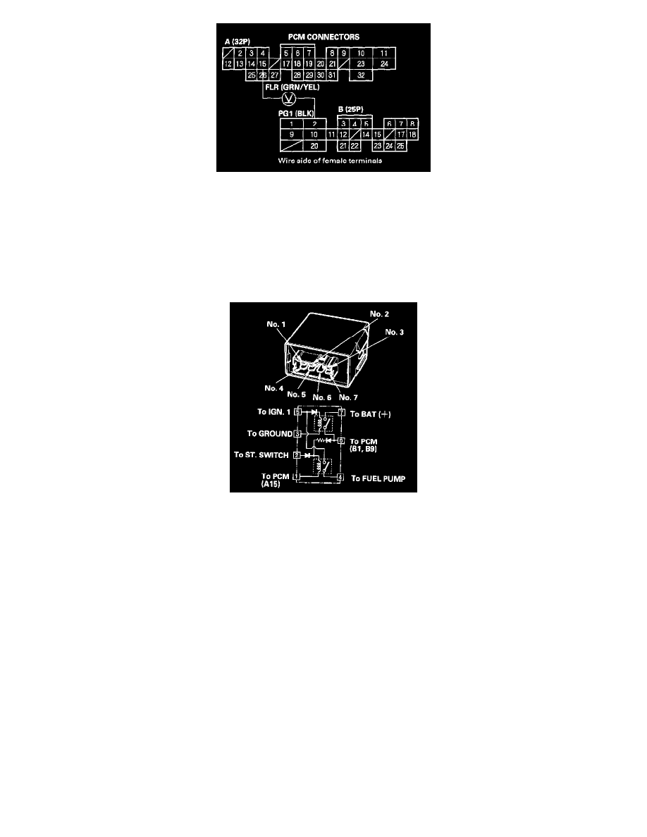
14. Remove the PGM-FI main relay.
15. Connect battery power to the PGM-FI main relay 7P connector terminal No.2 and connect ground to the PGM-FI main relay 7P connector
terminal No.1. Then check for continuity between the PGM-FI main relay 7P connector terminals No.5 and No.4.
NOTE: Use the terminal numbers shown. Ignore the terminal numbers molded into the relay.
Is there continuity?
YES - Go to step 16.
NO - Replace the PGM-FI main relay and reset.
16. Connect battery power to the PGM-FI main relay 7P connector terminal No.5, and connect ground to the PGM-FI main relay 7P connector
terminal No.3. Then check for continuity between the PGM-FI main relay 7P connector terminals No.7 and No.6.
Is there continuity?
YES - Go to step 17.
NO - Replace the PGM-FI main relay and reset.
17. Connect battery power to the PGM-FI main relay 7P connector terminal No.6, and connect ground to the PGM-FI main relay 7P connector
terminal No.1. Then check for continuity between the PGM-FI main relay 7P connector terminals No.5 and No.4.
Is there continuity?
YES - The PGM-FI main relay is OK.
NO - Replace the PGM-FI main relay and retest.