
Odyssey LX V6-3.5L (2000)
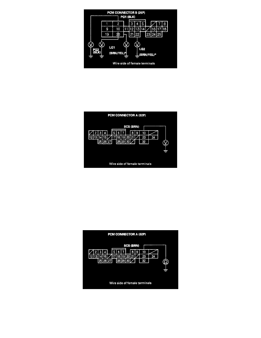
25. Turn the ignition switch ON (II), and measure voltage between body ground and PCM connector terminals B2, 810, B20 and 822 individually.
Is there less than 1.0 V?
YES - Substitute a known-good PCM and recheck. If the symptom/indication goes away, replace the original PCM.
NO - Repair the open in the wire(s) that had more than 1.0 V between G101 and the PCM (82, 810, B20, 822).
26. Turn the ignition switch OFF, then turn it back ON (11) and measure voltage between PCM connector terminal A10 and body ground.
Is there about 5 V (or battery voltage)?
YES - Go to step 27.
NO - Go to step 31.
27. Turn the ignition switch OFF.
28. Disconnect the negative cable from the battery.
29. Disconnect PCM connector A (32P).
30. Check for continuity between PCM connector terminal A10 and body ground.
Is there continuity?
YES - Repair short in the wire between the data link connector and the PCM (E29).
NO - Substitute a known-good PCM and recheck. If symptom/indication goes away, replace the original PCM.