
Odyssey LX V6-3.5L (2000)
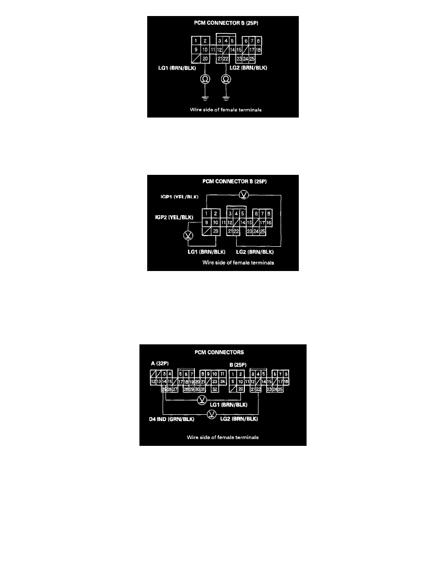
16. Check for continuity between body ground and B20 and B22 terminals.
Is there continuity?
YES: Go to step 17.
NO: Repair open in the wire(s) between the B20 or B22 terminal and ground (G101), or repair poor ground (G101).
17. Turn the ignition switch ON (II).
18. Measure the voltage between terminals B1 and B22, and between terminals B9 and B20.
Is there battery voltage?
YES: Go to step 19.
NO: Repair open or short in the wire between the B1 or B9 terminal and the PGM-FI main relay.
19. Turn the ignition switch OFF.
20. Reconnect the B (25P) connector to the PCM.
21. Connect the digital multimeter between the A14 and B20 or B22 terminals.
22. Turn the ignition switch ON (II).
Is there battery voltage for at least 2 seconds?
YES: Check for an open in the wire between the A14 terminal and the gauge assembly. If the wire is OK, check for a faulty D4 indicator light bulb
or a faulty printed circuit board in the gauge assembly.
NO: Go to step 23.
23. Turn the ignition switch OFF.
24. Disconnect PCM connector A (32P).