
Odyssey LX V6-3.5L (2000)
Is there continuity?
YES - Go to step 17.
NO - Go to step 18.
17. Disconnect the 3P connector from each of these sensors, one at a time, and check for continuity between body ground and PCM connector
terminal C19 and C28 individually.
-
Manifold Absolute Pressure (MAP) sensor
-
Exhaust Gas Recirculation (EGR) valve position sensor
-
Throttle Position (TP) sensor
-
Fuel Tank Pressure (FTP) sensor*
Is there continuity?
YES - Repair short to body ground in the wire between PCM (C19) and the MAP sensor, or PCM (C28) and the TP sensor, EGR valve position
sensor or FTP sensor*.
NO - Replace the sensor that made continuity to body ground go away when disconnected.
18. Disconnect the injectors and IAC valve connectors.
19. Reconnect the negative cable to the battery.
20. Turn the ignition switch ON (II).
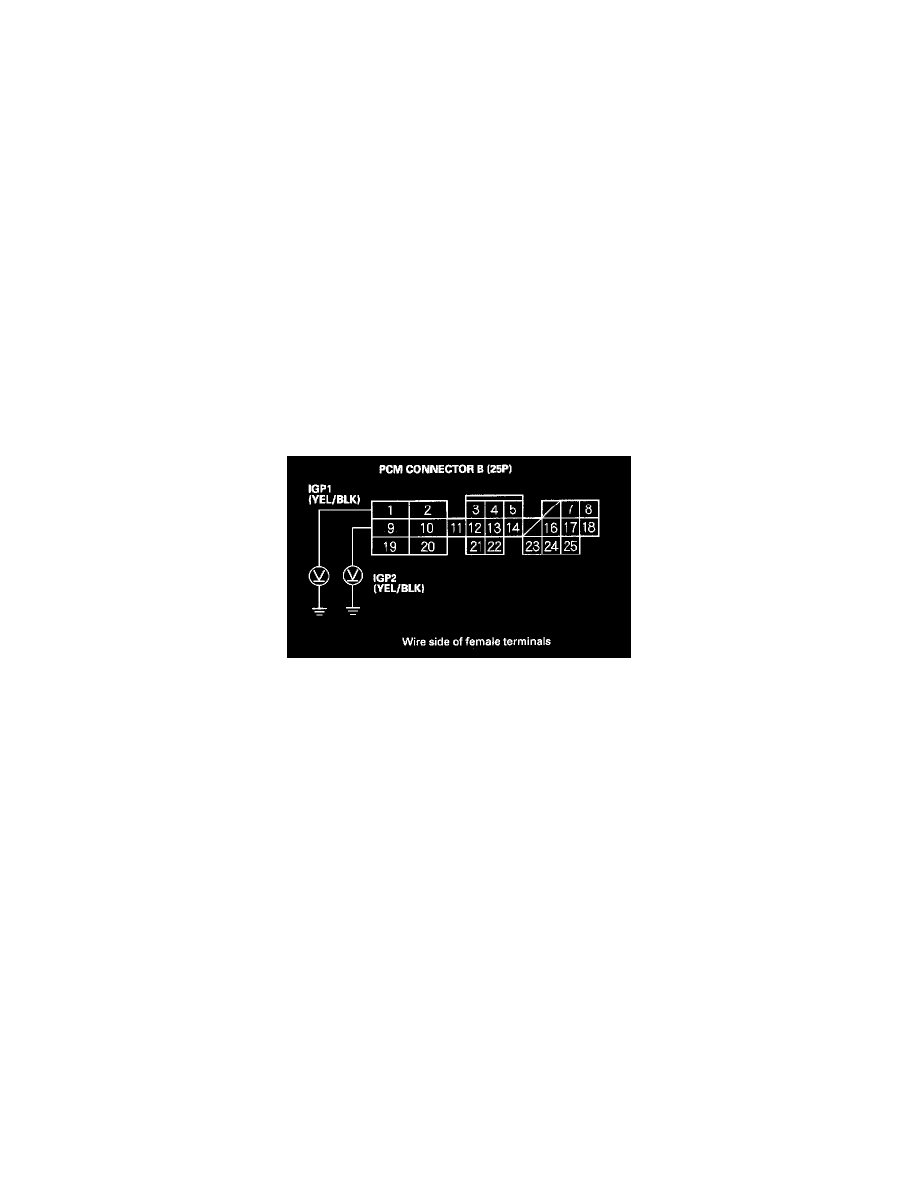
21. Measure voltage between body ground and the PCM connector terminals B1 and B9 individually.
Is there battery voltage?
YES - Go to step 22.
NO - Check for these problems:
-
An open in the wire(s) between the PGM-FI main relay and PCM connector terminals B1 and B9.
-
Poor connections at the PGM-FI main relay.
-
A faulty PGM-FI main relay. If necessary, repair or replace the part.
22. Disconnect the negative cable from the battery.
23. Reconnect the connectors to the sensors, then reconnect PCM connector C (31P).
24. Reconnect the negative cable to the battery.