
Pilot 2WD V6-3.5L (2006)
Is there continuity?
YES - Go to step 67.
NO - Repair open in the wire(s) between PCM (A22, B1, B36, B43, C1, C40) and body ground (G101).
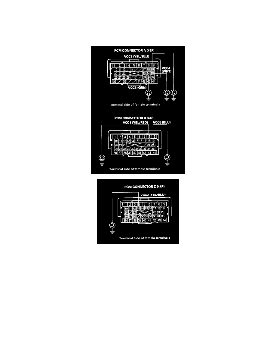
67. Disconnect the connector from each of the following sensors, one at a time, and check for continuity between body ground and PCM connector
terminal A19, A24, A25, B18, B19, and C13 individually.
-
MAP sensor
-
Output shaft (countershaft) speed sensor
-
EGR valve position sensor
-
Input shaft (mainshaft) speed sensor
-
APP sensor A
-
APP sensor B
-
TP sensor
-
FTP sensor
Is there continuity?
YES - Repair short to ground in the wire between the PCM and the appropriate sensor below.
-
MAP sensor
-
Output shaft (countershaft) speed sensor
-
EGR valve position sensor
-
Input shaft (mainshaft) speed sensor
-
APP sensor A