
Pilot 2WD V6-3.5L (2006)
Fuel Gauge Sender: Testing and Inspection
Fuel Gauge Sending Unit Test
Special Tools Required
Fuel sender wrench 07AAA-S0XA100
NOTE: For the fuel gauge sending system circuit diagram, refer to the gauges circuit diagram.
1. Check the No. 9 BACK UP LIGHT INSTRUMENT LIGHT (10 A) fuse in the driver's under-dash fuse/relay box before testing.
2. Turn the ignition switch OFF.
3. Remove the driver's side second row seat.
4. Cut the carpet, being careful not to cut the wire harness underneath it, then remove the access panel from the floor.
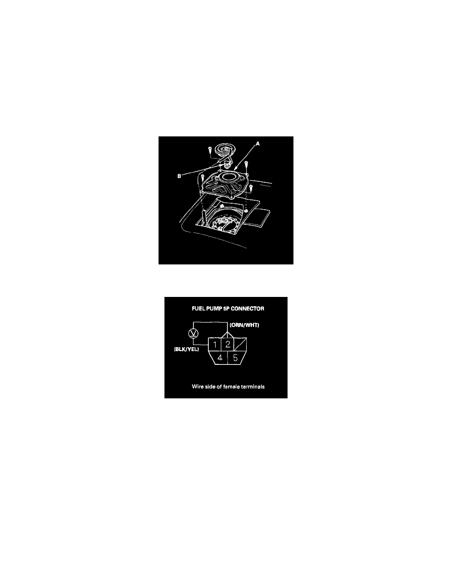
5. Remove the access panel (A) from the floor, then disconnect the fuel pump 5P connector (B).
6. Turn the ignition switch ON (II).
7. Measure voltage between fuel pump 5P connector terminals No.1 and No.2. There should be battery voltage.
-
If the voltage is as specified, go to step 8.
-
If the voltage is not as specified, check for:
-
an open in the ORN/WHT or BLK/YEL wire.
-
poor ground (G502).
8. Turn the ignition switch OFF.