
Prelude L4-1955cc 2000 (1987)
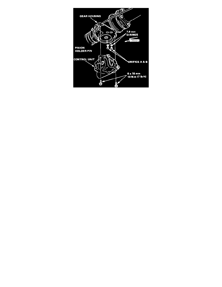
Fig. 3 Typical power steering control unit removal
4.
Remove orifice A and B with O-rings, Fig. 3.
5.
Remove valve body cap attaching bolts, then valve body cap.
6.
Remove O-ring and cap seal from valve body cap.
7.
Remove cut-off valve and spring from body, then separate valve body from housing.
8.
Remove valve port housing dowel pins and seal.
9.
Remove control valve O-ring, then inspect cut-off valve for scoring and scratches. If valve body is damaged, replace all three parts as a unit.
10.
Remove control valve rollers from valve body.
11.
Reverse procedure to assemble, noting the following:
a. Clean all disassembled parts prior to assembly.
b. Replace all O-rings and seals.
c. Coat plungers, control valve and cut-off valve with power steering fluid.
Steering Gear Disassembly
1.
With steering gear removed from vehicle, remove control unit. Refer to ``Control Unit Disassembly.''
2.
Remove boot bands, then boots. Straighten tie rod locks, then remove tie rods using two 19 mm wrenches.
3.
Push right end of cylinder rack into housing.
4.
Remove rack locknut and guide screw, then the 32 mm snap ring securing pinion lower ball bearing.
5.
Remove pinion from gear housing.
6.
Remove 15 mm snap ring, then separate lower ball bearing and pinion.
7.
Remove cylinder housing attaching bolts, then slide housing off rack.
8.
Remove rack bushing, cylinder spring and cylinder end seal from cylinder.
9.
Remove cylinder seal retainer, cap and steering rack from gear housing.
10.
Remove retainer washer and 46.5 mm O-ring from gear housing.
11.
Remove pinion dust seal retainer bolts, dust seal and retainer.
12.
Inspect pinion upper bearing. Replace if worn or damaged.
13.
Remove cylinder and seal retainer from rack.
14.
Remove two 35 mm O-rings from cylinder cap.
15.
Remove 24.5 mm O-ring and snap ring from seal retainer, then slide off cylinder cap.
16.
Remove cylinder end seal from retainer, then remove rack piston ring and 27.5 mm O-ring.
17.
Prior to assembly, clean all disassembled parts, replace all O-rings and seals.
18.
Install 27.5 mm O-ring in rack groove, then piston ring using suitable tool.
19.
Install both 33.5 mm O-rings on cylinder cap, then slide cylinder cap onto seal retainer.
20.
Install 28 mm snap ring and 24.5 mm O-ring on seal retainer.
21.
Grease sliding surface of cylinder end seal (white), then install seal in seal retainer. Both cylinder end seals are the same size, but are not
interchangeable. The white seal goes in end of retainer and black seal goes in end of cylinder housing.
22.
Install 46.5 mm O-ring and retainer washer into gear housing.
23.
Press seal retainer into gear housing, then stand housing on suitable workbench.