
Prelude L4-1958cc SOHC (1988)
Transmission Mode Switch: Testing and Inspection
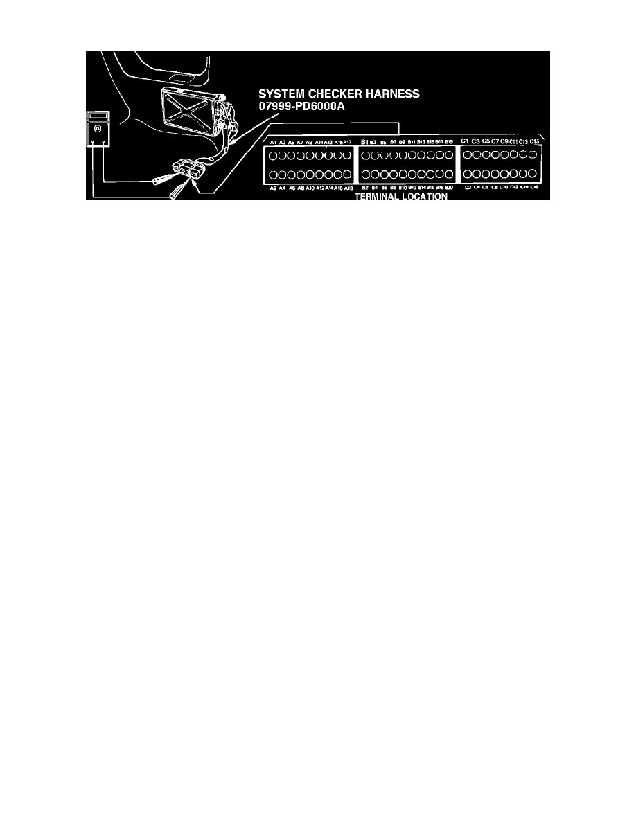
Fig. 23 System checker harness terminal identification
1988 Prelude
1.
Turn ignition switch to On position and observe shift indicator light while shifting into each range.
2.
If light does not work properly, check linkage and shift indicator and repair as necessary.
3.
Turn ignition switch to Off position and connect system checker harness between ECU and connector, Fig. 23, but disconnect B connector from
engine compartment wiring harness only, not the ECU.
4.
Turn ignition switch on and measure voltage between B7 (+) terminal and A18 (-) terminal.
5.
If voltage is not approximately 5 volts, substitute known good ECU and repeat test and, if voltage is now approximately 5 volts, replace original
ECU.
6.
If voltage is approximately 5 volts, reconnect B connector to engine compartment wiring harness and measure voltage between B7 (+) terminal
and A18 (-) terminal in Neutral position.
7.
If voltage is not below 1 volt, repair open in light green wire between ECU terminal B7 and combination meter and/or repair open in green wire
between combination meter and shift position console switch.
8.
If voltage is below 1 volt, measure voltage between B7 (+) terminal and A18 (-) terminal in Park position.
9.
If voltage is not below 1 volt, repair open in green/white wire between combination meter and shift position console switch.