
Prelude L4-2056cc DOHC (1990)
Engine Control Module: Description and Operation
Modes of Operation
Computerized Engine Control System
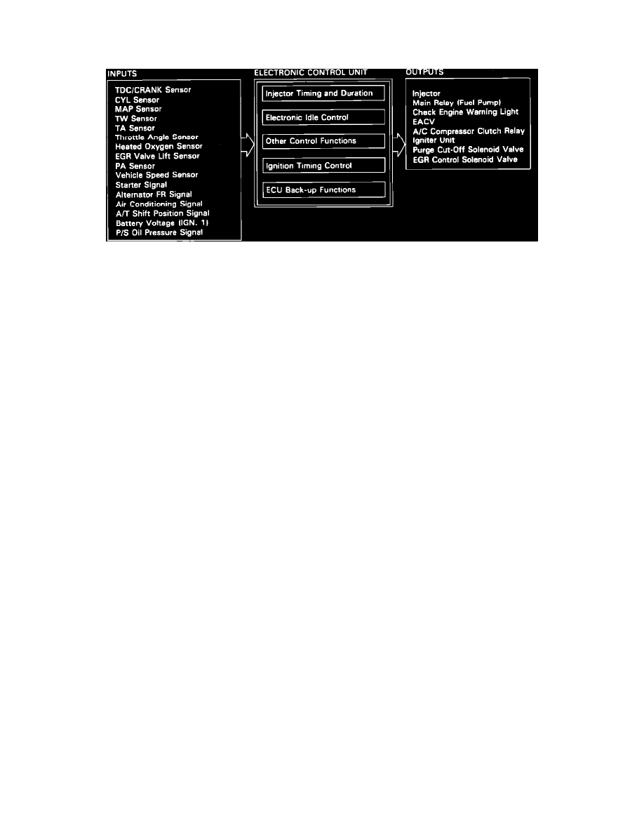
The PGM-FI Control (ECU) Unit in this vehicle is a dedicated microcomputer which controls virtually all engine functions. Based on information
received from the inputs, the ECU determines the current demands being placed on the engine. Once this is known, the ECU, based on the program
contained in permanent memory, uses the ECU outputs to tailor engine performance to more efficiently meet those demands. A generalized list of the
different control functions and the pertinent inputs and the outputs that control them are as follows:
INJECTOR TIMING AND DURATION
The ECU contains memories for the basic discharge durations at various engine speeds and manifold pressures. The basic discharge duration, after
being read out from the memory, is further modified by signals sent from various sensors to obtain the final discharge duration. The most vital of these
sensors are: Coolant Temperature (TW) sensor, Intake Air Temperature (TA) sensor, Oxygen sensor, and the Atmospheric Pressure (PA) sensor.
ELECTRONIC AIR CONTROL:
When the engine is cold, the A/C compressor is on, the transmission is in gear (A/T only) or the alternator is charging, the ECU controls current to the
EACV to maintain correct idle speed.
IGNITION TIMING CONTROL:
The ECU contains memories for basic ignition timing at various engine speeds and manifold pressures. Ignition timing is also adjusted for coolant
temperature.
OTHER CONTROL FUNCTIONS:
1. Starting Control
When the engine is started, the ECU provides a rich mixture.
2. Fuel Pump Control
a. When the ignition switch is initially turned on, the ECU supplies ground to the main relay which supplies current to the fuel pump for two
seconds to pressurize the fuel system.
b. When the engine running, the ECU supplies ground to the main relay which supplies current to the fuel pump.
c. When the engine is not running and the ignition is on, the ECU cuts ground to the main relay which cuts current to the fuel pump.
3. Fuel Cut-off Control
a. During deceleration with the throttle valve closed, current to the injectors is cut off to improve fuel economy at speeds over 1500 rpm.
b. Fuel cut-off action also takes place when engine speed exceeds 7000 rpm, regardless of the position of the throttle valve to protect the
engine from over-running.
4. A/C Compressor Clutch Relay
When the ECU receives a demand for cooling from the air conditioning system (compressor control unit), it delays the compressor from being
energized, and enriches the fuel mixture to assure smooth transition to the A/C mode.
5. Purge Cut-off Solenoid Valve
When the coolant temperature is below 158°F (70°C), the ECU supplies a ground to the purge cut-off solenoid valve which cuts vacuum to the
purge control valve.
6. EGR Control Solenoid Valve (EGR CSV)
When the EGR is required for control of oxides of nitrogen (NOx) emissions, the ECU supplies ground to the EGR CSV which supplies
regulated vacuum to the EGR valve.
ECU BACK-UP FUNCTIONS:
1. Fail-Safe Function
When an abnormality occurs in a signal from a sensor, the ECU ignores that signal and assumes a pre-programmed value that allows the engine