
Prelude L4-2056cc DOHC (1990)
Igniter: Testing and Inspection
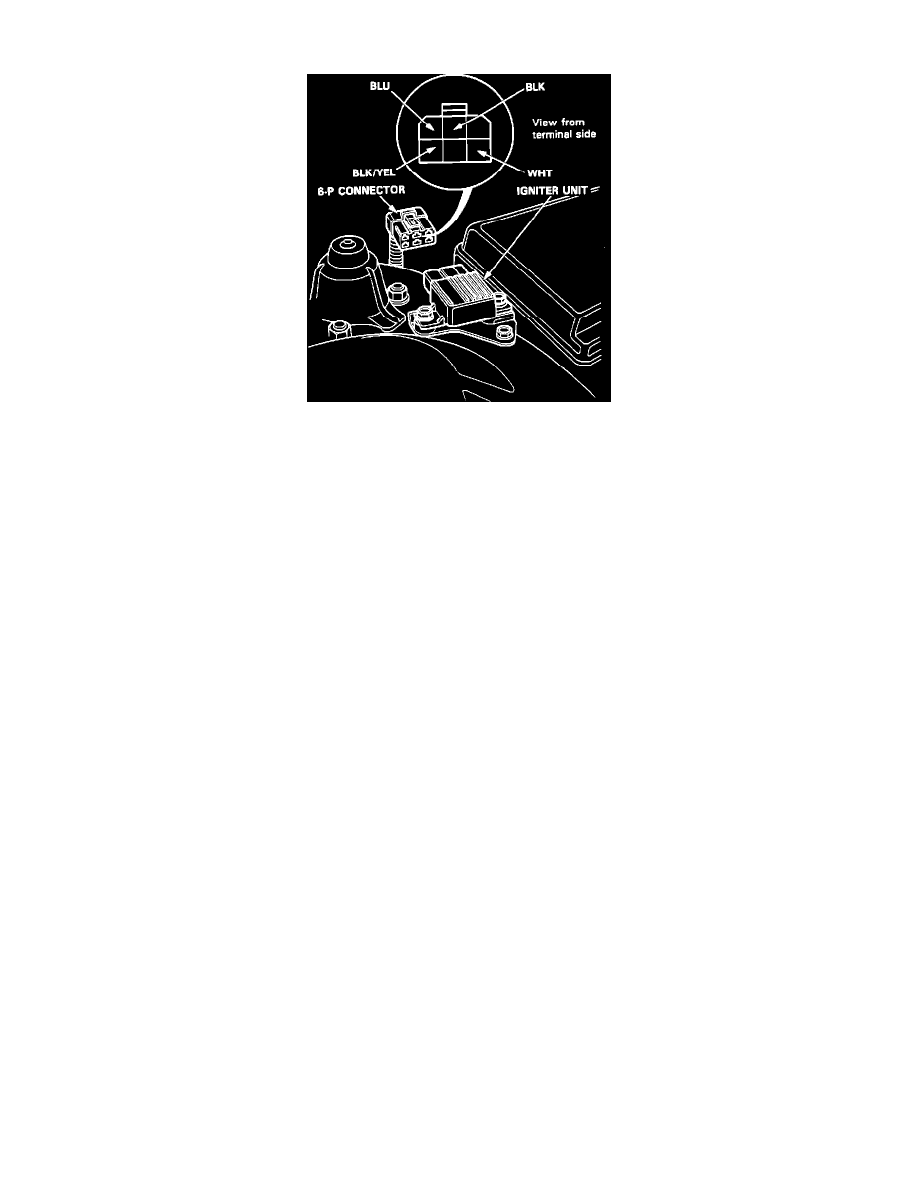
Igniter Assembly/Connector Identification
See CODE [15] IGNITION OUTPUT SIGNAL when the self-diagnostic LED blinks. Verify that the basic ignition system, fuel system, and
emission system are operating properly before performing an input test for the igniter unit.
NOTE: If the tachometer is operating properly the igniter unit is good and need not be checked.
1. Disconnect the 6-P connector from the igniter unit.
2. Turn the ignition switch ON. Check for voltage between the BLK/YEL wire and body ground. There should be battery voltage.
a. If there is no voltage, check the BLK/YEL wire between the ignition switch, ignition coil and igniter unit.
b. If there is voltage, go to step 3.
3. Turn the ignition switch ON. Check for voltage between the BLU wire and body ground. There should be battery voltage.
a. If there is no voltage, check for:
-BLU wire between the ignition coil and igniter unit.
-Ignition coil.
b. If there is voltage, go to step 4.
4. Check the WHT wire between the PGM-FI ECU and igniter unit.
5. If all test are normal, replace the igniter unit.