
Prelude L4-2056cc DOHC (1990)
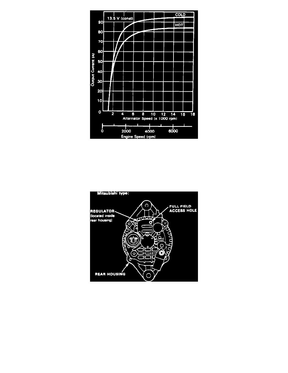
Fig. 7 Alternator Current Output Chart. 1989-91 Prelude
3.
To further test alternator and regulator, a Sun Vat 40 or other suitable charging system tester should be used. Follow tester manufacturer's
instructions for test connections and settings. When performing alternator and regulator tests with tester note the following:
a. When checking alternator output, operate engine at 2000 RPM with engine cooling fan off. Apply a load to charging system so that voltage
drops to no lower than 12 volts. Tester readings should be within 10 amps of readings indicated in Figs. 5 through 7. If readings are within
specification, charging system is operating properly, refer to CHARGE WARNING LAMP TEST. If readings are not within specification,
proceed to step b.
Fig. 8 Alternator Full Field Access Hole Location. Mitsubishi Units